


Chapter 4: Subsystem Connection and Operation
Subsystem Connection and Operation 4-23
BBU: If used, make sure the optional BBU has been installed correctly
in the single-controller enclosure.
Hard drives: Hard drives have been correctly installed in the drive
trays.
Drive trays: All the drive trays, whether or not they contain a hard
drive, have been installed into the subsystem.
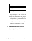
DIP switch settings: All the appropriate DIP switch settings have been
made. The hub has been enabled/disabled (as required) and the channel
speed has been properly configured.
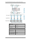
Cable connections: The subsystem has been correctly connected to
host computer(s), external networking devices, expansion enclosures,
and/or cascaded subsystems.
Power cords: The power cords have been connected to the PSUs on
the subsystem and plugged into the main power source.
Ambient temperature: All the subsystem components have been
acclimated to the surrounding temperature.
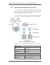
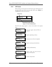
4.5.2 Power On Procedure
When powering on the subsystem, please follow these steps:
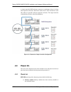
Step 1. Power on the Fibre Channel connection devices.
These devices include the FC switches and any other such
device that have been connected to the subsystems. Please
refer to the documentation that came with your networking
devices to see their power on procedure.
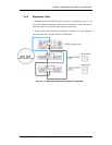
Step 2. Power on the cascaded subsystems or the expansion JBODs
that are not connected directly to the host computers.
Step 3. Power on the subsystem.
The subsystems should be powered on before the host
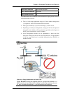
computers. Turn the power switch on. (See Figure 4-13) One
(1) power switch that controls all PSUs is shielded by an anti-
tamper plastic cover.