


1-4
Switch 4210G 48-Port
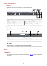
Front Panel
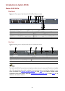
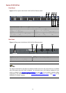
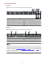
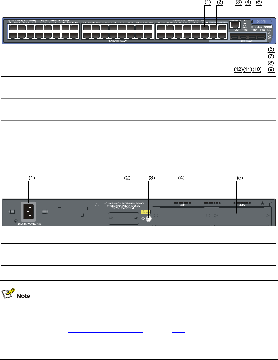
Figure 1-3 Front panel of the Switch 4210G 48-Port Ethernet switch
(1) 10/100/1000 Base-T auto-sensing Ethernet port
(2) 10/100/1000 Base-T auto-sensing Ethernet port status LED
(3) Console port (4) Seven-segment LED
(5) Port mode LED (Mode) (6) System status LED (PWR)
(7) RPS status LED (RPS) (8) Interface module 1 status LED (MOD1)
(9) Interface module 2 status LED (MOD2) (10) Port status LED mode switching button
(11) 1000Base-X SFP port (12) 1000Base-X SFP port status LED
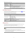
Rear Panel
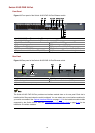
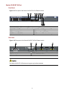
Figure 1-4 Rear panel of the Switch 4210G 48-Port Ethernet switch
(1) AC power input (2) RPS power input (shipped with a protective cover)
(3) Grounding screw (4) Interface module slot 1 (MOD1)
(5) Interface module slot 2 (MOD2)
The Switch 4210G 48-Port provides two interface module slots on its rear panel. Each slot is installed
with a filler panel when the switch is shipped. You can select one or two interface modules for your
switch as needed. See
Optional Interface Modules on page 1-15 for the interface module models
supported by the Switch 4210G, and see
Connecting the RPS Power Cord on page 3-14 for the
installation of interface modules.