


3-10
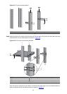
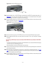
Step1 Cut the PGND cable to a proper length according to the distance between the switch and the grounding
strip.
Step2 Peel 5 mm (0.20 in.) of insulation sheath using a wire stripper, and then insert the naked metal part
through the black insulation covering into the end of the OT terminal.
Step3 Secure the metal part of the cable to the OT terminal with a crimper, and then cover it with the insulation
covering. Then heat the insulation covering with a blowing machine to let it completely cover the metal
part.
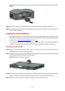
Step4 Connect the OT terminal to the grounding pole of the grounding strip, and then fasten it with a hex nut.
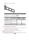
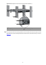
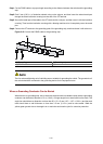
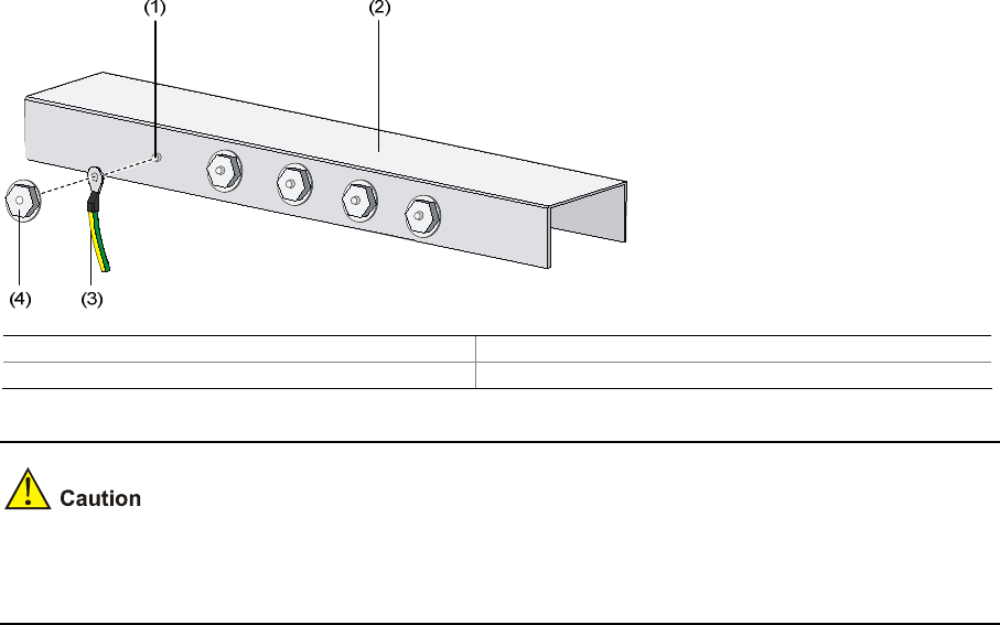
Figure 3-12 Connect the PGND cable to the grounding strip
(1) Grounding post (2) Grounding strip
(3) PGND cable (4) Hex nut
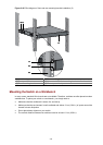
The fire main and lightning rod of a building are not suitable for grounding the switch. The ground wire of
the switch should be connected to the grounding device for the equipment room.
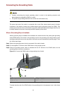
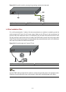
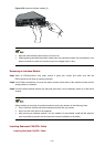
Where a Grounding Conductor Can be Buried
When there is no grounding strip, but an area with exposed earth is available nearby where a grounding
conductor can be buried, hammer a 0.5 m (1.64 ft.) or longer angle iron or steel tube into the earth. The
angle iron should have a dimension no less than 50 × 50 × 5 mm (1.97 × 1.97 × 0.20 in.) and the steel
tube should have a wall thickness no less than 3.5 mm (0.14 in.) and be zinc-coated. Weld the
yellow-green ground wire to the angel iron or steel tube and treat the joint for corrosion protection.