


3-14
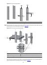
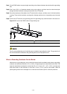
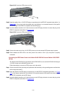
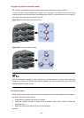
Figure 3-19 Connect an RPS power cord (1)
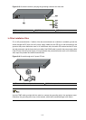
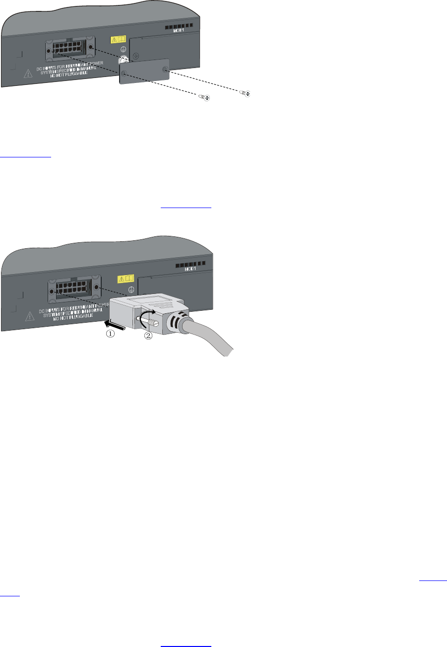
Step3 Keep the upside of the +12 VDC RPS plug on top and plug it in the RPS DC receptacle (see callout 1 in
Figure 3-20). (If you plug it with the upside down, the insertion is not smooth because of the specific
structure design of the RPS DC receptacle and the RPS plug.)
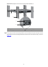
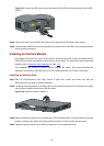
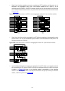
Step4 Use a flat-blade screwdriver to fix the two screws on the RPS plug clockwise to secure the plug to the
RPS DC receptacle (see callout 2 in
Figure 3-20).
Figure 3-20 Connect an RPS power cord (2)
Step5 Connect the other end of the +12 VDC RPS power cord to the external RPS power supply system.
Step6 Check whether the RPS LED on the front panel of the switch is ON. If yes, the power is properly
connected.
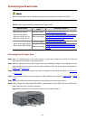
Connecting the RPS Power Cord of the Switch 4210G PWR 24-Port and Switch 4210G PWR
48-Port
The Switch 4210G PWR 24-Port and Switch 4210G PWR 48-Port can work with RPS1000-A3 using its
–54 V/25 A output and a 0404A053 power cord.
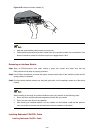
Follow these steps to connect an RPS power cord to the switch:
Step1 Connect one end of the grounding wire (delivered with the switch) to the grounding screw and the other
end to the ground nearby.
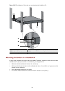
Step2 Keep the upside of the RPS plug on top and plug it in the RPS DC receptacle (see callout 1 in
Figure
3-21). (If you plug it upside down, the insertion is not smooth because of the specific structure design of
the RPS DC receptacle and the RPS plug.)
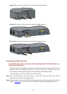
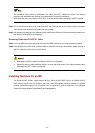
Step3 Use a flat-blade screwdriver to fix the two screws on the RPS plug clockwise to secure the plug to the
RPS DC receptacle (see callout 2 in
Figure 3-21).