


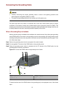
3-12
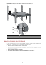
Connecting the Power Cords
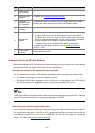
Make sure that the ground wire has been properly connected before powering on the switch.
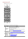
Table 3-3 Power cord connection methods of the Switch 4210G
Switch module
Power supply
mode
Connection method
AC power supply Connecting the AC Power Cord Switch 4210G 24-Port
Switch 4210G 48-Port
Switch 4210G NT 24-Port
Switch 4210G NT 48-Port
RPS power supply
Connect RPS power cords of the Switch 4210G
(excluding Switch 4210G PWR 24-Port and
Switch 4210G PWR 48-Port)
AC power supply Connecting the AC Power Cord
Switch 4210G PWR 24-Port
Switch 4210G PWR 48-Port
RPS power supply
Connecting the RPS Power Cord of the Switch
4210G PWR 24-Port and Switch 4210G PWR
48-Port
Connecting the AC Power Cord
Step1 Wear an ESD-preventive wrist strap, ensure a good skin contact and make sure that the
ESD-preventive wrist strap is properly grounded.
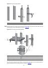
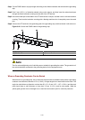
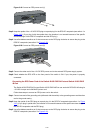
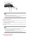
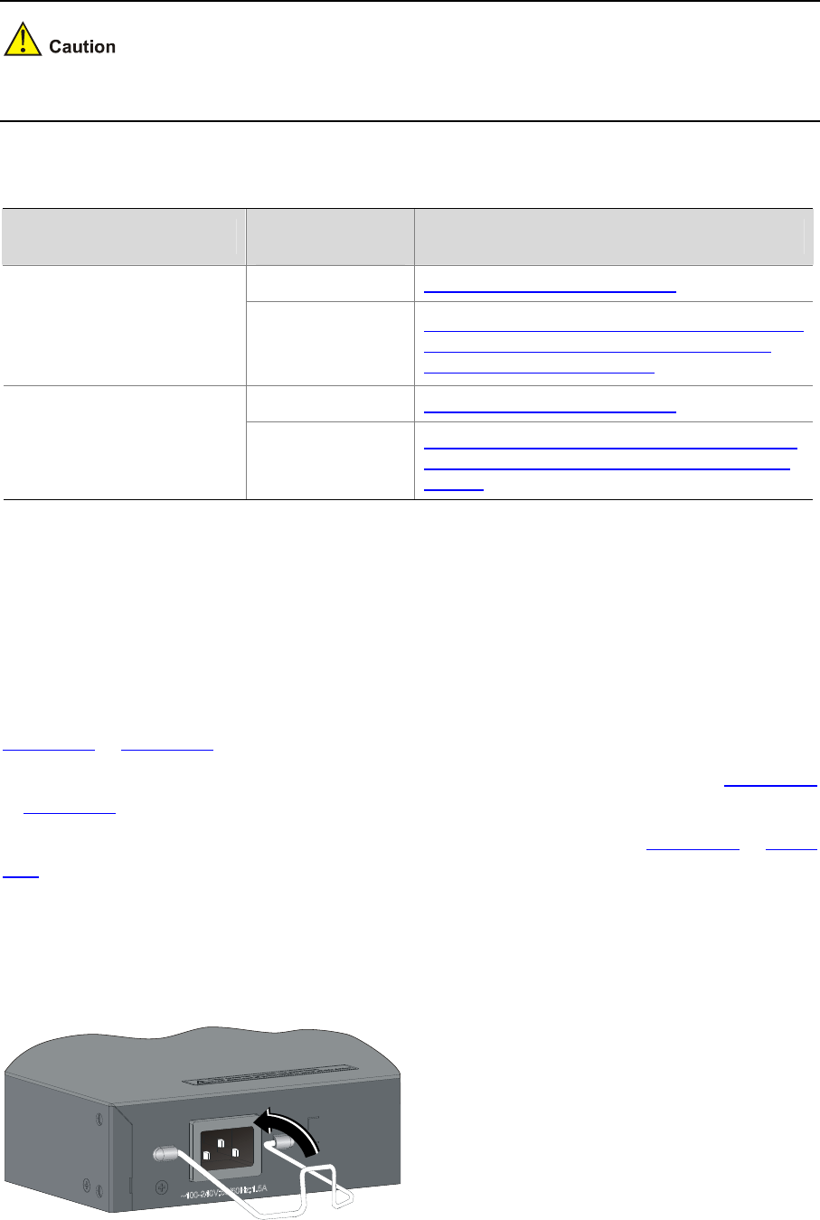
Step2 Install the bail latch to prevent the AC power cord from accidentally falling off. Fix the bail latch into the
holes located at the two sides of the AC power receptacle. Then pull the bail latch upwards (see in
Figure 3-15 or Figure 3-17).
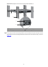
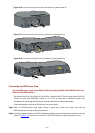
Step3 Connect one end of the AC power cord to the AC receptacle on the switch (see callout 1 in
Figure 3-16
or
Figure 3-18).
Step4 Pull the bail latch down to secure the plug to the AC receptacle (see callout 2 in
Figure 3-16 or Figure
3-18).
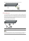
Step5 Connect the other end of the AC power cord to the external AC power supply system.
Step6 Check whether the system status LED (PWR) on the front panel of the switch is ON. If the LED is ON, it
shows the power cord is properly connected.
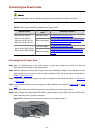
Figure 3-15 Connect an AC power cord to a horizontal AC power socket (1)