


3-6
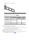
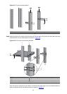
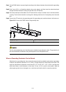
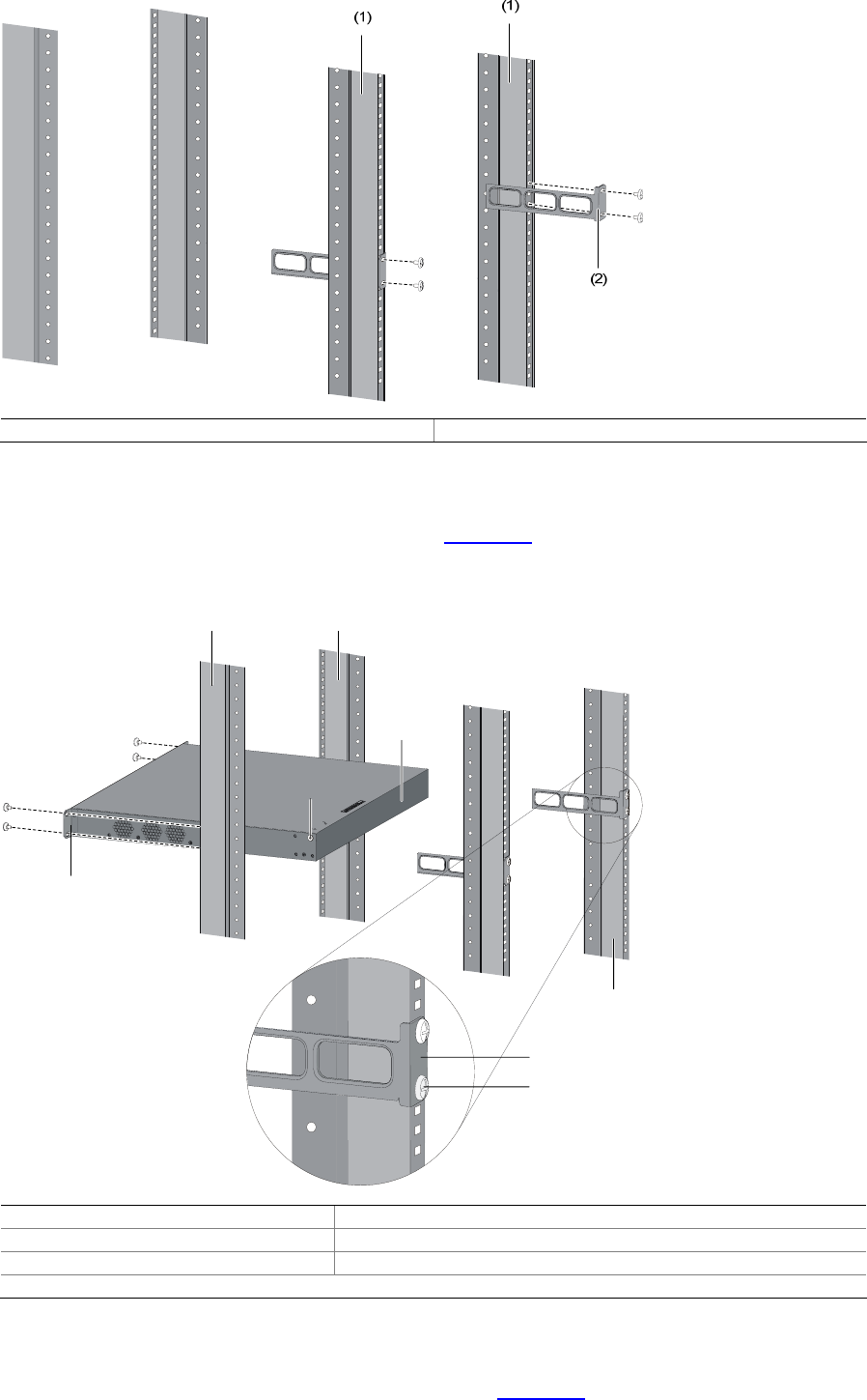
Figure 3-7 Fix rear mounting brackets
(1) Rear square-holed post (2) Rear mounting bracket
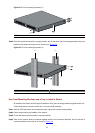
Step6 Hold the bottom of the switch with one hand and the front part of the switch with the other hand, and
push the switch into the cabinet gently, as shown in
Figure 3-8.
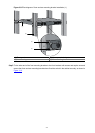
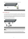
Figure 3-8 Fix front and rear mounting brackets
(1) (1)
(7)
(3)
(4)
(5)
(6)
(2)
(1) Front square-holed post (2) Load-bearing screw: Used to bear the weight
(3) Rear panel (4) Rear square-holed post
(5) Rear mounting bracket (6) Screw used to fix rear mounting brackets to rear posts
(7) Front mounting bracket
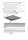
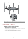
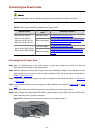
After the switch is pushed into the cabinet, ensure that the upper edge of rear mounting brackets is
tightly contacted with the load-bearing screw, as shown in
Figure 3-9.