


3-18
Installation Flow for an IRF
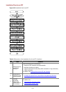
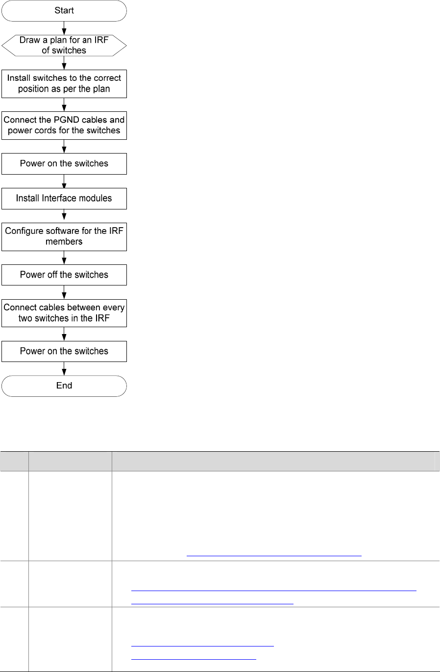
Figure 3-24 Installation flow for an IRF
Table 3-4 Description of the installation flow for an IRF of switches
No Task Remarks
1
Draw a plan for
an IRF with
switches
Take the following into consideration:
z Number of IRF members and the bandwidth
z Interface modules and cables
z Physical connection mode( daisy chain connection or ring connection)
z Cable connection
For details, see
Drawing a Plan for an IRF with Switches.
2
Install the IRF
members to the
correct position
For detailed installation procedures, see:
z Installing the Switch into a 19-Inch Rack Using Mounting Brackets.
z Mounting the Switch on a Workbench.
3
Connect
grounding
cables and
power cords for
the switches
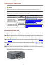
For details, see:
z Connecting the Grounding Cable
z Connecting the Power Cords