


3-5
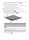
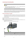
Step5 Place the switch on the tray horizontally, slide the tray into the cabinet, and fix the other end of mounting
brackets to the front brackets with crews and captive nuts, as shown in
Figure 3-5.
Use Front and Rear Mounting Brackets to Install a Switch
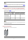
Only the Switch 4210G PWR 24-Port and Switch 4210G PWR 48-Port support installation using front
mounting brackets together with rear mounting brackets.
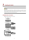
Follow these steps to install a switch into a 19-inch standard cabinet:
Step1 Wear an ESD-preventive wrist strap and ensure a good skin contact and grounding.
Step2 Check the grounding and stability of the cabinet.
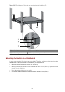
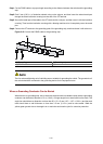
Step3 Take out the screws which are packed together with the front mounting brackets, and fix one end of
mounting brackets to the switch, as shown in
Figure 3-4.
Step4 Take out the load-bearing screws (packed together with the rear mounting brackets) and place them in
a proper position on the sides of the switch, as shown in
Figure 3-6.
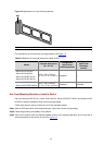
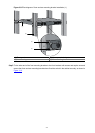
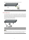
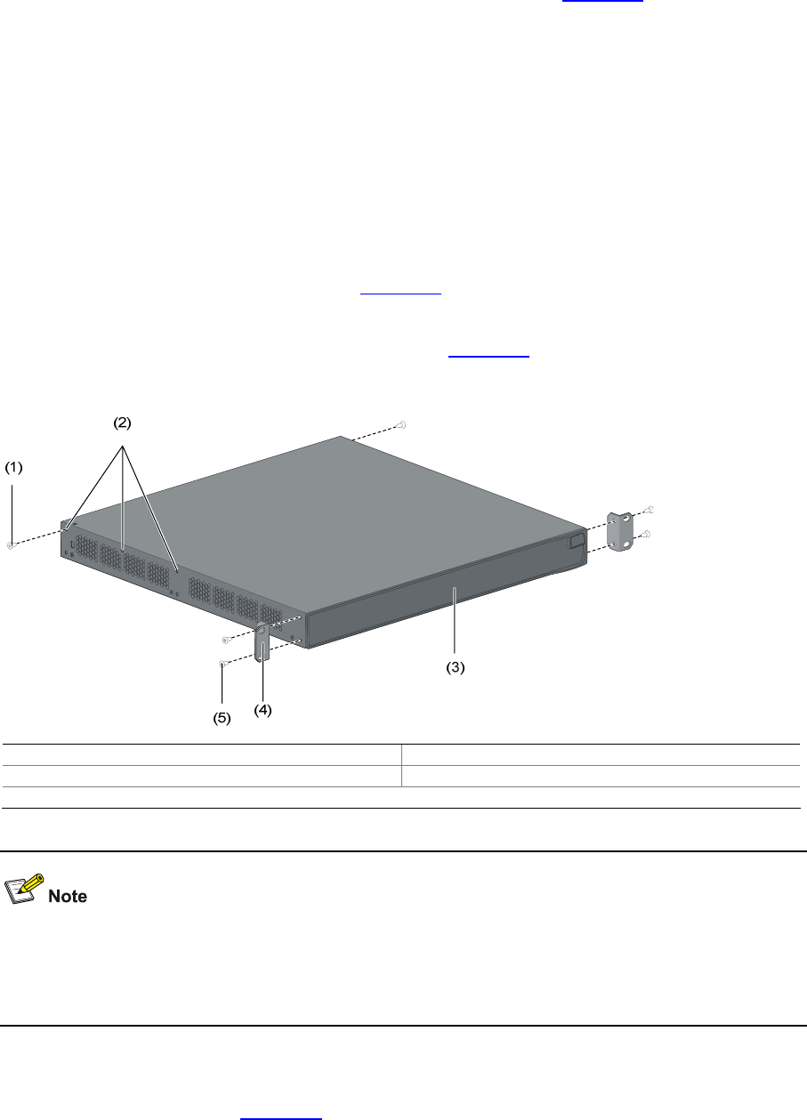
Figure 3-6 Fix front mounting brackets and load-bearing screws
(1) Load-bearing screw (2) Optional positions for Load-bearing screw
(3) Front panel (4) Front mounting bracket
(5) Screw used to fix front mounting brackets to the switch
There are three positions to mount a load-bearing screw on both sides of a switch. You should select a
proper position according to the actual requirements. The rear mounting brackets tightly contacted with
the load-bearing screws can support the switch.
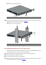
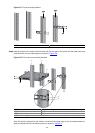
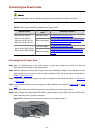
Step5 Select a position to install the switch and fix the rear mounting brackets to the rear posts with screws
and captive nuts, as shown in
Figure 3-7.