


1-7
Switch 4210G NT 24-Port
Front Panel
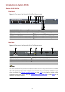
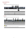
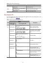
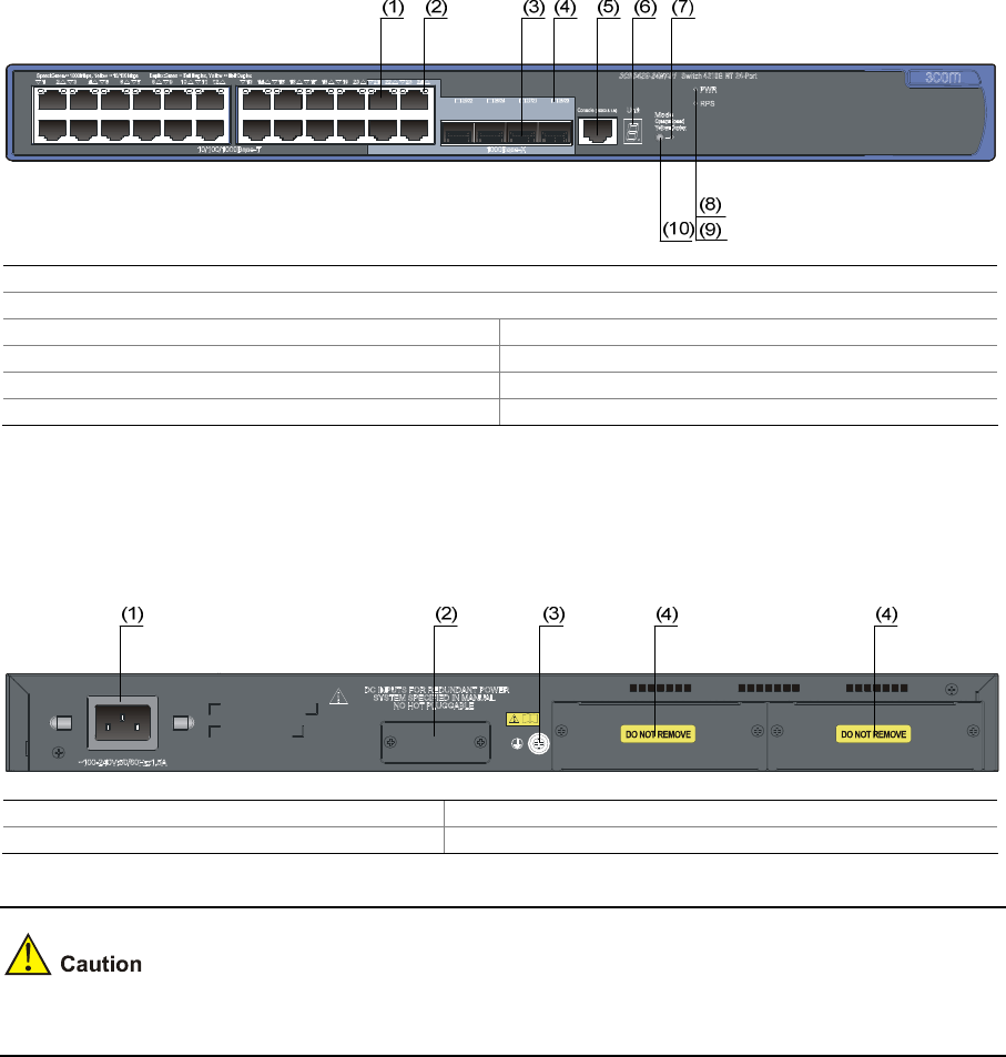
Figure 1-9 Front panel of the Switch 4210G NT 24-Port Ethernet switch
(1) 10/100/1000 Base-T auto-sensing Ethernet port
(2) 10/100/1000 Base-T auto-sensing Ethernet port status LED
(3) 1000 Base-X SFP port (4) 1000Base-X SFP port status LED
(5) Console port (6) Seven-segment LED
(7) Port mode LED (Mode) (8) System status LED (PWR)
(9) RPS status LED (RPS) (10) Port status LED mode switching button
Rear Panel
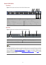
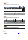
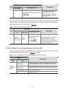
Figure 1-10 Rear panel of the Switch 4210G NT 24-Port Ethernet switch
(1) AC power input (2) RPS power input (shipped with a protective cover)
(3) Grounding screw (4) “DO NOT REMOVE” label
The Switch 4210G NT 24-Port does not support any interface modules.