


3-9
Connecting the Grounding Cable
z Correctly connecting the chassis grounding cable is crucial to the lightning protection and
electromagnetic susceptibility (EMS) of a switch.
z The power and grounding terminals in this section are for illustration only.
The power input end of the switch is connected with a noise filter, whose central ground is directly
connected to the chassis, forming the so-called chassis ground (commonly known as PGND). This
chassis ground must be securely connected to the earth so that the faradism and leakage electricity can
be safely released to the earth, enhancing the EMS capability of the switch.
When a Grounding Strip is Available
When a grounding strip is available at the installation site, attach one end of the yellow-green grounding
cable (PGND cable) of the switch to the grounding screw on the grounding strip (the grounding screw
and the grounding hole are on the rear panel of the switch and are marked with a grounding sign). To do
this, follow these steps:
Step1 Remove the grounding screw from the rear panel of the switch chassis.
Step2 Put the supplied OT terminal of the PGND cable on the grounding screw.
Step3 Fasten the grounding screw, which is attached with the OT terminal of the PGND cable, into the
grounding screw hole with a screwdriver.
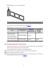
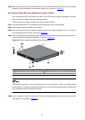
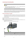
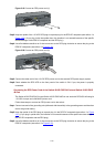
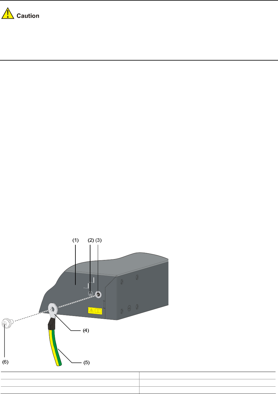
Figure 3-11 Connect the PGND cable to the grounding hole of switch
(1) Rear panel of the switch (2) Grounding sign
(3) Grounding hole (4) OT terminal
(5) PGND cable (6) Grounding screw
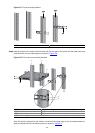
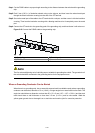
To attach the other end of the PGND cable to the grounding strip in the equipment room, follow these
steps: