


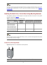
3-7
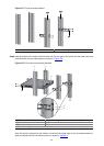
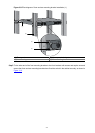
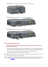
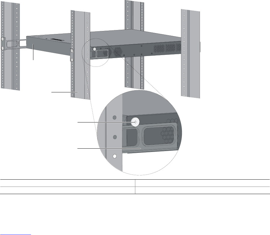
Figure 3-9 Effect diagram of front and rear mounting bracket installation (1)
(1)
(2)
(3)
(4)
(1) Rear panel (2) Rear square-holed post
(3) Load-bearing screw (4) Rear mounting bracket
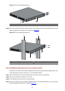
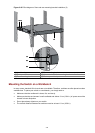
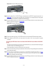
Step7 Fix the other end of the front mounting brackets to the front brackets with screws and captive nuts and
ensure that front and rear mounting brackets have fixed the switch in the cabinet securely, as shown in
Figure 3-10.