


Overview of Virtual LANs 5-3
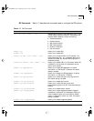
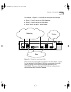
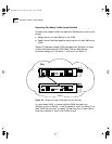
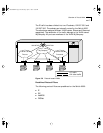
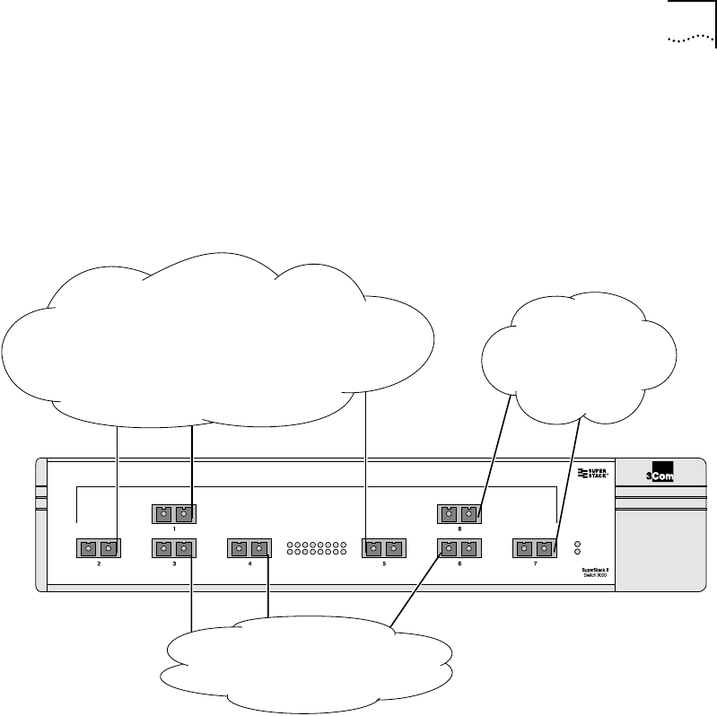
For example, in Figure 5-1, the VLANs are configured as followings:
■ Ports 1, 2, and 5 are part of VLAN Marketing
■ Ports 3, 4, and 6 are part of VLAN Sales
■ Ports 7 and 8 are part of VLAN Finance
Figure 5-1 Example of a port-based VLAN
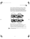
Even though they are physically connected to the same Switch, in order
for the members of the different VLANs to communicate, the traffic
must go through the IP routing functionality provided in the
Switch 9000. This means that each VLAN must be configured as a
router interface with a unique IP address.
Marketing
Finance
Sales
SW9000.BK Page 3 Wednesday, April 1, 1998 11:00 AM