


Chapter 2
AT7/AT7E
2-6
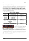
2-3. Installing System Memory
This motherboard provides four 184-pin DDR DIMM sites for memory expansion. The DDR SDRAM
DIMM sockets support 8 M x 64 (64 MB), 16M x 64 (128 MB), 32 M x 64 (256 MB), 64 M x 64 (512
MB) and 128 M x 64 (1024 MB) or double density DDR SDRAM DIMM modules. Minimum memory is
64 MB and the maximum memory is 3 GB (Unbuffered, PC 1600 and PC 2100) / 2GB (Unbuffered,
PC 2700) or 3.5 GB (Registered, PC 1600 and PC 2100) / 3 GB (Registered, PC 2700) DDR SDRAM.
There are four memory module sockets on the system board (for a total of eight banks). In order to create
a memory array, following rules must be followed.
! Supports single and double density DDR DIMMs.
Table 2-1. Valid Memory Configurations
Bank Memory Module Total Memory
Bank 0, 1
(DDR DIMM1)
64 MB, 128 MB, 256 MB,
512 MB, 1024 MB
64 MB ~ 1 GB
Bank 2, 3
(DDR DIMM2)
64 MB, 128 MB, 256 MB,
512 MB, 1024 MB
64 MB ~ 1 GB
Bank 4, 5
(DDR DIMM3)
64 MB, 128 MB, 256 MB,
512 MB, 1024 MB
64 MB ~ 1 GB
Bank 6, 7
(DDR DIMM4)
64 MB, 128 MB, 256 MB,
512 MB, 1024 MB
64 MB ~ 1 GB
Total System Memory for Unbuffered DDR DIMM
(PC 1600/PC 2100)
64 MB ~ 3 GB
Total System Memory for Registered DDR DIMM
(PC 1600/PC 2100)
64 MB ~ 3.5 GB
Total System Memory for Unbuffered DDR DIMM
(PC 2700)
64 MB ~ 2 GB
Total System Memory for Registered DDR DIMM
(PC 2700)
64 MB ~ 3 GB
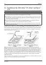
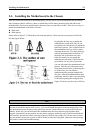
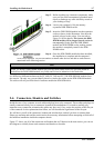
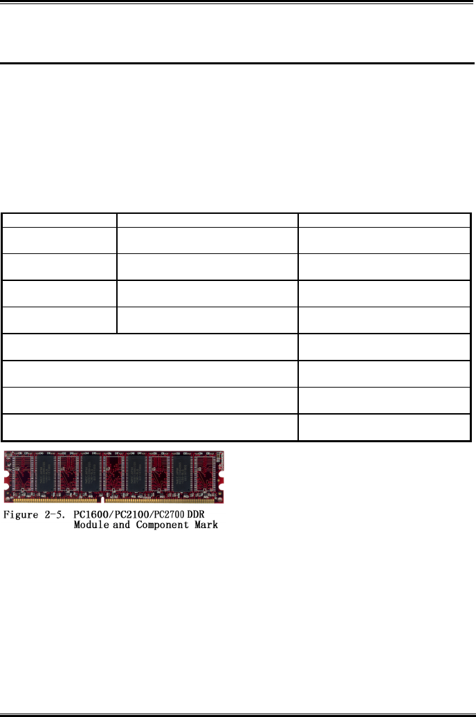
Generally, installing DDR SDRAM modules to your
motherboard is an easy thing to do. You can refer to
Figure 2-5 to see what a 184-pin PC 1600, PC 2100
and PC 2700 DDR SDRAM module looks like.
Unlike installing SIMMs, DIMMs may be
“snapped” directly into the socket. Note: Certain
DDR DIMM sockets have minor physical differences. If your module doesn't seem to fit, please do not
force it into the socket as you may damaged your memory module or DDR DIMM socket.
The following procedure will show you how to install a DDR DIMM module into a DDR DIMM socket.
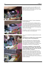
Step 1. Before you install the memory module, please place the computer power switch in the off
position and disconnect the AC power cord from your computer.
Step 2. Remove the computer’s chassis cover.