


Installing the Motherboard
User’s Manual
2-13
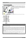
Note
Before you clear the CMOS, you have to first turn the power off (including the +5V standby power).
Otherwise, your system may work abnormally.
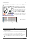
After updating your BIOS and before boot up, please clear the CMOS first. Then put the jumper to its
default position. After that, you can reboot your system and ensure that your system is working fine.
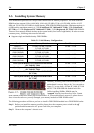
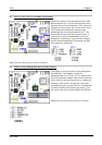
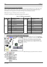
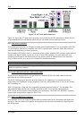
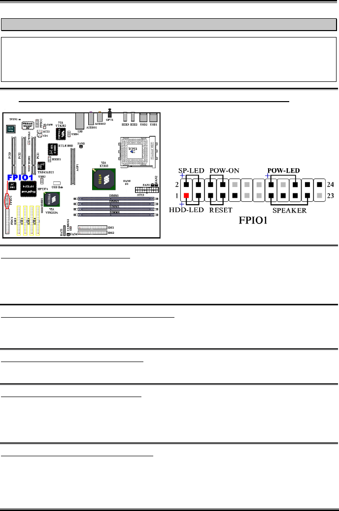
(8). FPIO1 Headers: The Headers for Chassis’s Front Panel Indicators and Switches
FPIO1 are for switches and indicators for the
chassis’s front panel, there are several functions that
come from this header. You have to watch the pin
position and the orientation, or you may cause LED
do not light up. Figure below shows you the FPIO1
functions of the pins.
FPIO1 (Pin 1 & 3): HDD LED Header
Attach the cable from the case’s front panel HDD LED to this header. If you install it in the wrong
direction, the LED light will not illuminate correctly.
Note: Watch the HDD LED pin position and the orientation.
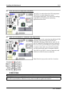
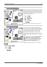
FPIO1 (Pin 5 & 7): Hardware Reset Switch Header
Attach the cable from the case’s front panel Reset switch to this header. Press and hold the reset button
for at least one second to reset the system.
FPIO1 (Pin 15-17-19-21): Speaker Header
Attach the cable from the system speaker to this header.
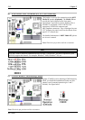
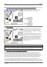
FPIO1 (Pin 2 & 4): Suspend LED Header
Insert the two-threaded suspend LED cable into this header. If you install it in the wrong direction, the
LED light will not illuminate correctly.
Note: Watch the Suspend LED pin position and the orientation.
FPIO1 (Pin 6 & 8): Power On Switch Header
Attach the cable from the case’s front panel power on switch to this header.