


Chapter 2
AT7/AT7E
2-14
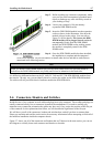
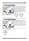
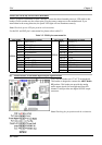
FPIO1 (Pin 16-18-20): Power On LED Headers
There is a specific orientation for pins 1 through 3. Insert the three-threaded power on LED cable to this
header. Check to make sure the correct pins go to the correct connectors on the motherboard. If you
install them in the wrong direction, the power LED light will not illuminate correctly.
Note: Watch the power LED pin position and orientation.
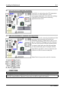
For the PN1 and PN2 pin’s count-name list, please refer to table 2-2.
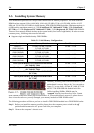
Table 2-2. FPIO1 pin count name list
PIN Name Significance of signal PIN Name Significance of signal
PIN 1 HDD LED (+) PIN 2 SP-LED (+)
PIN 3 HDD LED (-) PIN 4 SP-LED (-)
PIN 5 Reset SW (-) PIN 6 PWR-ON (+)
PIN 7 Reset SW (+) PIN 8 PWR-ON (-)
PIN 9 No Connection PIN 10
No Pin
PIN 11 No Pin PIN 12 No Pin
PIN 13 No Pin PIN 14 No Pin
PIN 15 Speaker (+5V) PIN 16 PWR LED (+)
PIN 17 Speaker (GND) PIN 18 No Pin
PIN 19 Speaker (GND) PIN 20 PWR LED (-)
PIN 21 Speaker (Driver) PIN 22 No Connection
FPIO1
PIN 23 No Pin
FPIO1
PIN 24 No Connection
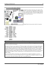
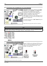
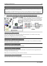
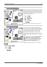
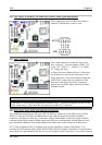
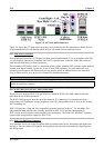
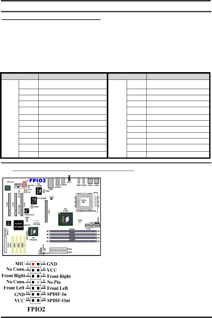
(9). FPIO2 Header: Front Panel Input/Output Signals Header
You’ll see this header on AT7/AT7E motherboard.
This header is designed to connect the ABIT Media
XP product. This header can provide the analog
audio output signals for front right and front left
channel. It also provides one digital S/PDIF output
connector.
Note: Watching the pin position and the orientation