


Installing the Motherboard
User’s Manual
2-19
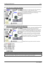
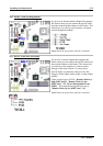
(18). Audio1 and Audio2 Connectors
Audio1 and Audio2 connectors are audio connectors for analog audio signal in or out.
Mic In Connector: You can connect the plug from the microphone to this connector. Do not connect
other audio (or signal) sources to this connector.
Line In Connector: You can connect the TV adapter audio output signal, or external audio sources, like
a CD walkman, video camcorder, VHS recorder audio output signal plug to this connector. Your audio
software can control the input level for the line-in signal.
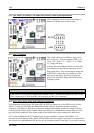
Front Right + Left Channel Connector: You can connect the plug from the front channel speakers or
front channel amplifier to this connector. Please make sure you are connect to the front channel speakers
or front channel amplifier correctly, otherwise you may get the wrong sound positioning.
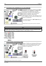
Rear Right + Left Channel Connector: You can connect the plug from the rear channel speakers or rear
channel amplifier to this connector. Please make sure you are connect to the rear channel speakers or rear
channel amplifier correctly, otherwise you may get the wrong sound positioning.
Center + Subwoofer Channel Connector: You can connect the plug from the center/subwoofer channel
speakers or center/subwoofer channel amplifier to this connector. Please make sure you are connect to the
center/subwoofer channel speakers or center/subwoofer channel amplifier correctly, otherwise you may
get the wrong sound positioning.
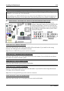
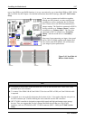
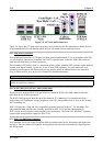
(19). 10/100 Mb LAN Port Connector
This motherboard provides one built-in 10/100 Mb LAN port, this jack is for connecting the RJ-45 cable
from the local area network hub to your computer. We suggest you use the category 5 UPT (Unshielded
Twisted Pair) or STP (Shielded Twisted Pair) cable to make this connection. The connection length from
the hub to the computer is best to be kept under 100 meter.
The green LED shows the connection situation. If the network active well, this LED will light on. The
yellow LED shows if the data is active or not. If the computer is translating or receiving data from the
network, this LED will flicker.
Note
This chapter contains many color drawing diagram and photos, we strongly recommend you to read
this chapter use the PDF file we gave you that store in the CD-Title. It will provide you the better look
and clearly color identify.