


Chapter 3 55
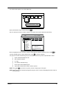
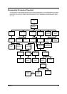
Disassembly Procedure Flowchart
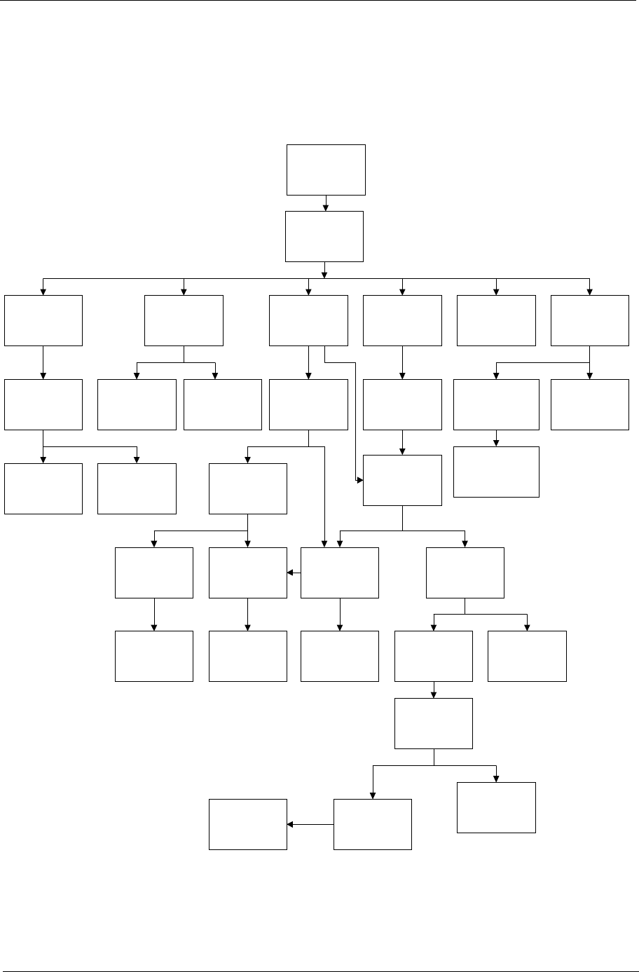
The flowchart on the succeeding page gives you a graphic representation on the entire disassembly sequence
and instructs you on the components that need to be removed during servicing. For example, if you want to
remove the main board, you must first remove the keyboard, then disassemble the inside assembly frame in
that order.
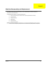
START
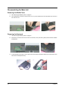
Battery
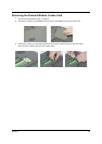
HDD Cover
HDD Module
HDD
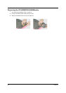
DIMM Cover
Modem Board DIMM
HDD Bracket
Cx1
Hx1
Ax2
Middle CoverKeyboard
Coaxial CableRTC Battery
MINI PCI Plate
Touch Pad
Module
Upper Case
LCD Module
(See Next
Page)
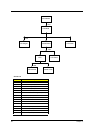
CPU Fan Sink
CPU Speakers
Daughter
Board
Main Board
Fx2 Cx2 Cx2
Lx1
Cx6
Kx4
Cx6
Cx2
Cx1
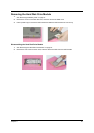
CD/DVD ROM
Module
CD/DVD ROM
Drive
CD/ DVD
ROM Drive
Chassis
CD/DVD ROM
Transfer Board
Video Capture
Kit Covers
Lower Case
Mx2
I/O Port
Chassis
PCMCIA
Socket
Modem Cable
Ax2
Ox2
Jx4
Ax1
Ix2
Gx4
Two Antennas
Gx2
Wireless LAN
board