


21
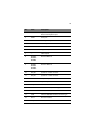
System LED indicators
This section discusses the different LED indicators located on the:
• Front panel
• Hot-plug HDD carrier
• LAN port
• Power supply module
Knowing what each LED indicator signifies can aid in problem
diagnosis and troubleshooting.
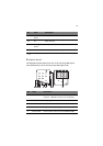
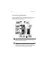
Front panel LED indicators
The five LED indicators mounted on the front panel allow the constant
monitoring of basic system functions. These indicators remain visible
even when the bezel door is closed.
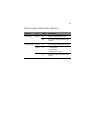
Indicator Color Status Description
Power Green On The system has AC power and is
powered on.
Blinking The system is in standby mode.
HDD activity Green Blinking There is an ongoing HDD activity.
Amber On An system hard drive failed.
Status/fault
1
1 The status/fault LED indicator is only enabled when the optional BMC module is installed
on the mainboard. To purchase this option, contact your local Acer representative.
Green On System in normal mode.
Amber On Critical system threshold breach
Access the Setup utility and view the
system event log for details.
LAN port 1/2
connection
Green On Network connection is established.
Blinking Network connection is established
and is running at supported speed.
Off Network connection is not
established.