


The ICX-250 Unit System Basics 13
Issue 1, September 1998 ADCP-62-023
© 1998, ADC Telecommunications, Inc.
T
he ICX-250 Unit
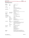
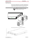
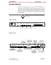
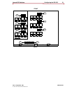
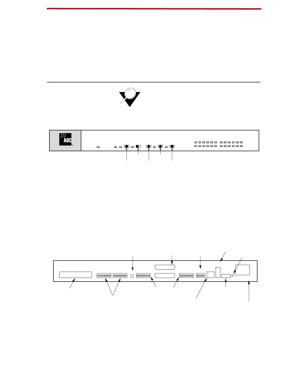
The ICX-250 comes equipped with either 12 FXS (model 240212) or 24
FXS (model 240224) analog voice ports depending on which model you
purchase. Each unit is designed to allow easy accessibility to switches and
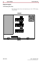
electrical connectors. The diagrams below illustrate the front and rear
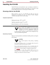
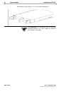
layout of the unit. The diagram on the next page illustrates the internal
layout of the unit.
Note:
The 12 FXS or 24 FXS models are not field
upgradeable.
ICX-250 - Front Panel
ICX-250 - Rear Panel
ICX-250
1357911131517192123
2 4 6 8 10 12 14 16 18 20 22 24
FXS Status Channel
Data Loop 2
Lcl. / Off / Net.
Data Loop 1
Lcl. / Off / Net.
T1 Loop
Net. / Off / Lcl.
1 / Off / 2Off / QRSS
T1 Status
T1 Loop
Test Pattern
Test Pattern
T1 Test
Self Check
11261-A
120 VAC–.6A 60Hz
24/48 VDC
+ – G
T1
Rx
Tx
T1 Line
T1Data 2Data 2Data 11121324
Alm.
Data 1
FXS Loopback
FXS Loop Pairs
11264-A
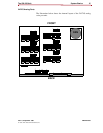
25 PAIR AMPHENOL
CONNECTOR FOR 24
FXS TIP AND RING PAIRS
DIP SWITCHES TO SET
LOOPBACK FOR EACH
FXS CHANNEL
ALARM RELAY
FOR EXTERNAL
ALARM SYSTEM
TWO DB25 FEMALE
CONNECTORS FOR
DATA PORT 1 AND 2
SIGNALS
DIP SWITCHES USED FOR DATA
PORT 1 AND 2 CONFIGURATION
DIP SWITCHES
USED FOR T1
INTERFACE
CONFIGURATION
RJ48 CONNECTOR
FOR TRANSMIT AND
RECEIVE TIP AND
RING PAIRS
DUAL BANTAM
JACK
(MONITOR JACKS)
TERMINAL BLOCK FOR
DC POWER SUPPLY
EARTH GROUND
POWER INPUT FOR
120 VAC RECEPTACLE