


External DIP Switches Configuring the ICX-250 37
Issue 1, September 1998 ADCP-62-023
© 1998, ADC Telecommunications, Inc.
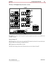
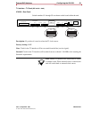
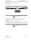
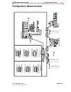
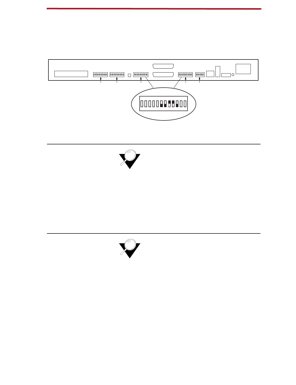
Data Port 1 and 2 - Starting Timeslot
(
DIP switch - back
)
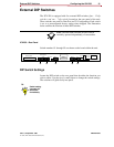
ICX-250 - Rear Panel
Switch numbers S1 through S5 are shown on the board within the unit.
Note:
Starting time slots will always be odd
numbered (i.e. 1, 3, 5, 7, 9, etc.).
Description:
S2 position 6, 7, 8 and 9 selects the starting timeslot (1,3,5,7,9,etc.) for Data Port 2.
S3 position 6, 7, 8 and 9 selects the starting timeslot (1,3,5,7,9,etc.) for data port 1.
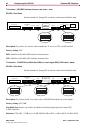
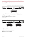
Factory Setting:
All switches are set to zero (data ports not active).
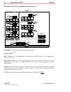
Starting Timeslot:
Selects first T1 timeslot that data from Data Port 1 and/or 2 will be mapped.
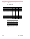
(1,3,5,7,9....23). Please refer to Decimal/Binary Conversion Table (see page 36) to aid in selecting
the starting timeslot. Drawing above indicates switch settings using timeslot 6 as the starting timeslot.
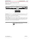
Factory Setting:
All switches are set to zero (data
ports not active).
120 VAC–.6A 60Hz
24/48 VDC
+ – G
T1
Rx
Tx
T1 Line
T1Data 2Data 2Data 11121324
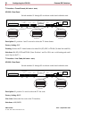
ON DIP
10
1
23456789101112
Alm.
Data 1
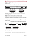
FXS Loopback
FXS Loop Pairs
S5 S4 S3 S2 S1
11272-A
Data 1 / Data 2