


External DIP Switches Configuring the ICX-250 39
Issue 1, September 1998 ADCP-62-023
© 1998, ADC Telecommunications, Inc.
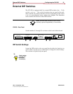
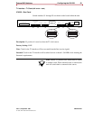
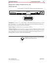
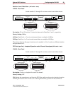
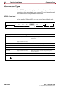
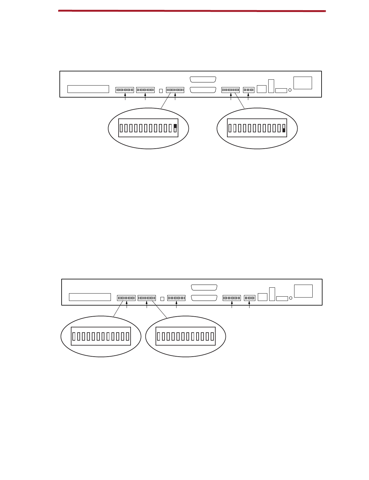
Data Port 1 and 2 Data Rate -
(
DIP switch - back
)
ICX-250 - Rear Panel
Switch numbers S1 through S5 are shown on the board within the unit.
Description:
S2 and S3 position 12 selects the data rate for Data Ports 2 and 1, respectively.
Factory Setting:
56Kbps
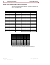
64 Kbps:
Data Ports1 or 2 receive and transmit data at a multiple of 64 Kbps.
56 Kbps:
Data Ports 1 or 2 receive and transmit data at a multiple of 56 Kbps.
The options shown on this page do not have to be matched. i.e. Port 1 can have a different interface
and speed than Port 2.
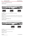
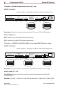
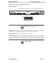
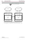
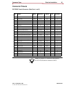
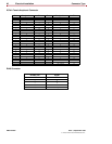
FXS Ports (per line) - Loopback Operation and/or Channel Unassigned
(
DIP switch - back
)
ICX-250 - Rear Panel
Switch numbers S1 through S5 are shown on the board within the unit.
Description:
Used to set loopback for each FXS channel.
Factory Setting:
OFF
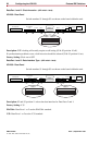
ON:
Breaks the connections to and from the FXS Ports and loops the receive data back onto the
transmit path towards the T1. In the case of unassigned channels, provides an idle termination.
120 VAC–.6A 60Hz
24/48 VDC
+ – G
T1
Rx
Tx
T1 Line
T1Data 2Data 2Data 11121324
ON DIP
10
1
23456789101112
Alm.
Data 1
FXS Loopback
FXS Loop Pairs
S5 S4 S3 S2 S1
11274-A
Data 1
ON DIP
10
1
23456789101112
Data 2
64 Kbps 56 Kbps
120 VAC–.6A 60Hz
24/48 VDC
+ – G
T1
Rx
Tx
T1 Line
T1Data 2Data 2Data 11121324
ON DIP
10
1
23456789101112
Alm.
Data 1
FXS Loopback
FXS Loop Pairs
S5 S4 S3 S2 S1
11275-A
FXS Loopback
ON DIP
10
1
23456789101112
FXS Loopback