


52 ICX-250 Diagnostics Testing
ADCP-62-023 Issue 1, September 1998
© 1998, ADC Telecommunications, Inc.
Testing
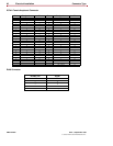
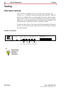
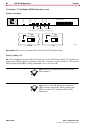
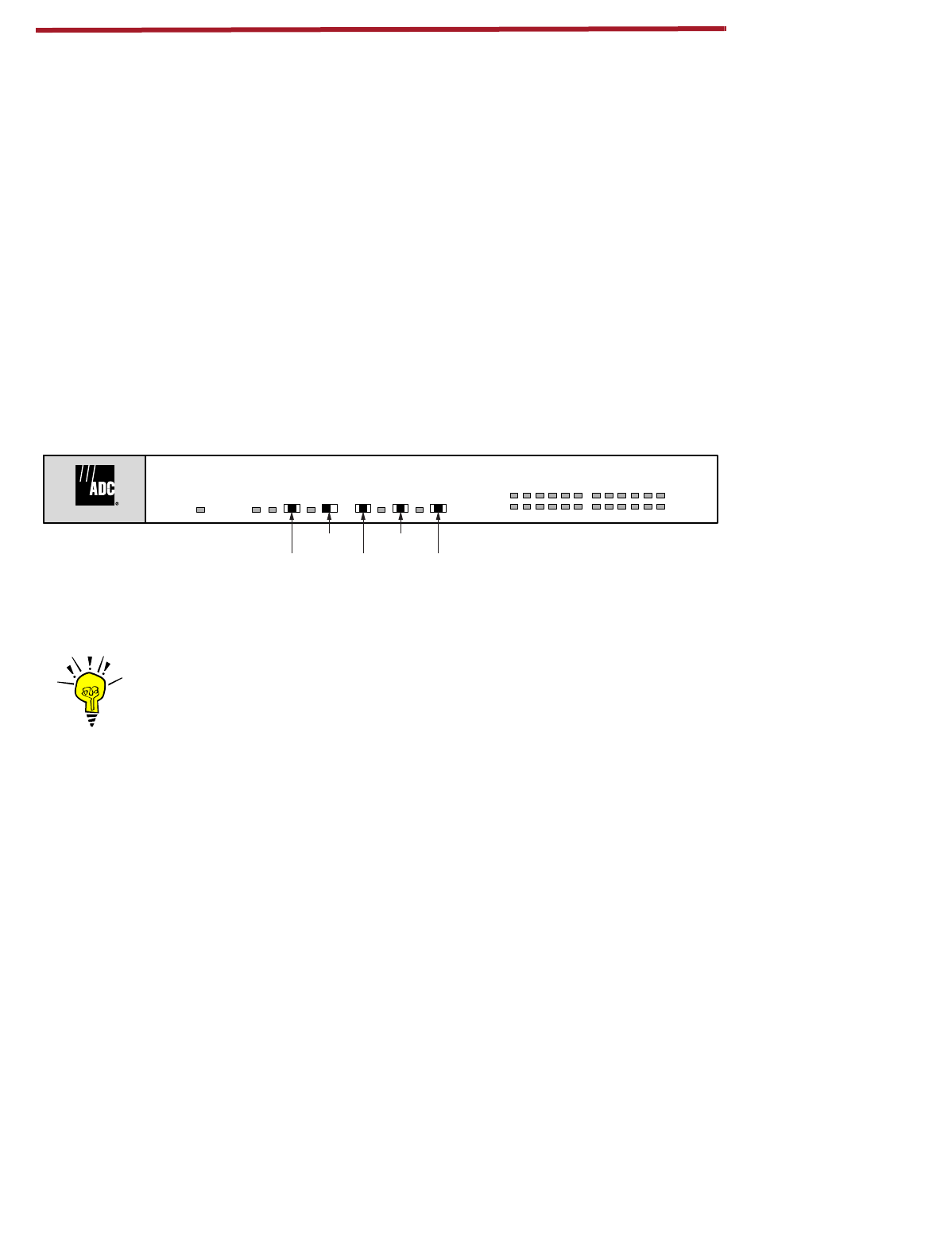
Slide Switch Settings
The ICX-250 is equipped with five external slide switches (
four - 3
position, one - 2 position)
located on the front panel of the unit. They are
used for T1 and Data Port test and Loopback Transmit / Receive paths.
Each switch is factory set to the off position. The switches should be
checked to be sure positioning hasn’t changed during shipment. The
illustration below outlines the location of the slide switches.
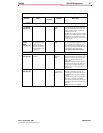
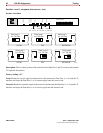
Locate the slide switch on the front panel that implements the function
desired. Use the end of a small object or the tip of your finger to change
the switch settings.
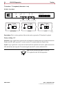
ICX-250 - Front Panel
ICX-250
1357911131517192123
2 4 6 8 10 12 14 16 18 20 22 24
FXS Status Channel
Data Loop 2
Lcl. / Off / Net.
Data Loop 1
Lcl. / Off / Net.
T1 Loop
Net. / Off / Lcl.
1 / Off / 2Off / QRSS
T1 Status
T1 Loop
Test Pattern
Test Pattern
T1 Test
Self Check
11261-A
ICX-250
1357911131517192123
2 4 6 8 10 12 14 16 18 20 22 24
FXS Status Channel
Data Loop 2
Lcl. / Off / Net.
Data Loop 1
Lcl. / Off / Net.
T1 Loop
Net. / Off / Lcl.
1 / Off / 2Off / QRSS
T1 Status
T1 Loop
Test Pattern
Test Pattern
T1 Test
Self Check
11261-A
TIP
Switch setting
changes will
take effect
immediately.