


34 Configuring the ICX-250 External DIP Switches
ADCP-62-023 Issue 1, September 1998
© 1998, ADC Telecommunications, Inc.
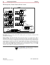
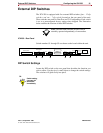
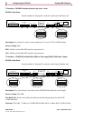
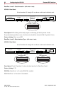
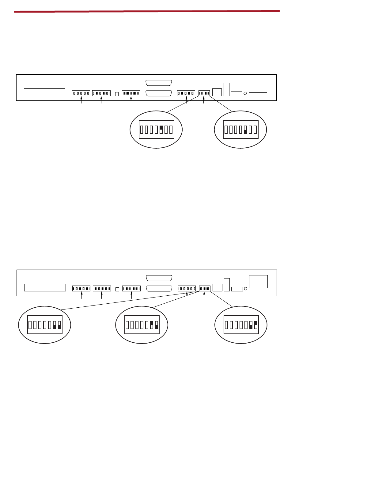
T1 Interface - CSU/DSX Interface
Selection (
Dip switch - back
)
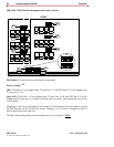
ICX-250 - Rear Panel
Switch numbers S1 through S5 are shown on the board within the unit.
Description:
S1 position 5 is used to select whether the T1 acts as a CSU or DSX interface.
Factory Setting:
CSU
DSX:
SlimLine will exhibit DSX interface characteristics.
CSU:
SlimLine will exhibit CSU interface characteristics.
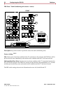
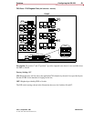
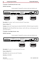
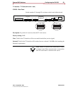
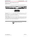
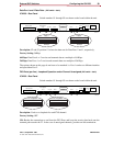
T1 Interface -
CSU/DSX Line Build Out (CSU) or Line Length (DSX) (
DIP switch - back
)
ICX-250 - Rear Panel
Switch numbers S1 through S5 are shown on the board within the unit.
Description:
S1 position 6 and 7 are used to select CSU/DSX line build out or line length.
Factory Setting:
CSU 0dB
Line Build Out:
Selects one of three line build out and line length options for either CSU
or DSX interfaces.
Selections:
CSU 0 dB, –7.5 dB and –15.0 dB; DSX 0.6 dB at 250 ft, 1.8 dB at 500 ft, 3.0 dB at 700 ft.
120 VAC–.6A 60Hz
24/48 VDC
+ – G
T1
Rx
Tx
T1 Line
T1Data 2Data 2Data 11121324
ON DIP
1234567
Alm.
Data 1
FXS Loopback
FXS Loop Pairs
S5 S4 S3 S2 S1
11269-A
T1
ACCEPT
ON DIP
1234567
T1
IGNORE
120 VAC–.6A 60Hz
24/48 VDC
+ – G
T1
Rx
Tx
T1 Line
T1Data 2Data 2Data 11121324
ON DIP
1234567
Alm.
Data 1
FXS Loopback
FXS Loop Pairs
S5 S4 S3 S2 S1
11270-A
T1
–7.5 dB
ON DIP
1234567
T1
–15.0 dB
ON DIP
1234567
T1
0 dB