


Connector Type Electrical Installation 45
Issue 1, September 1998 ADCP-62-023
© 1998, ADC Telecommunications, Inc.
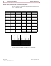
Connector Pinouts
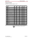
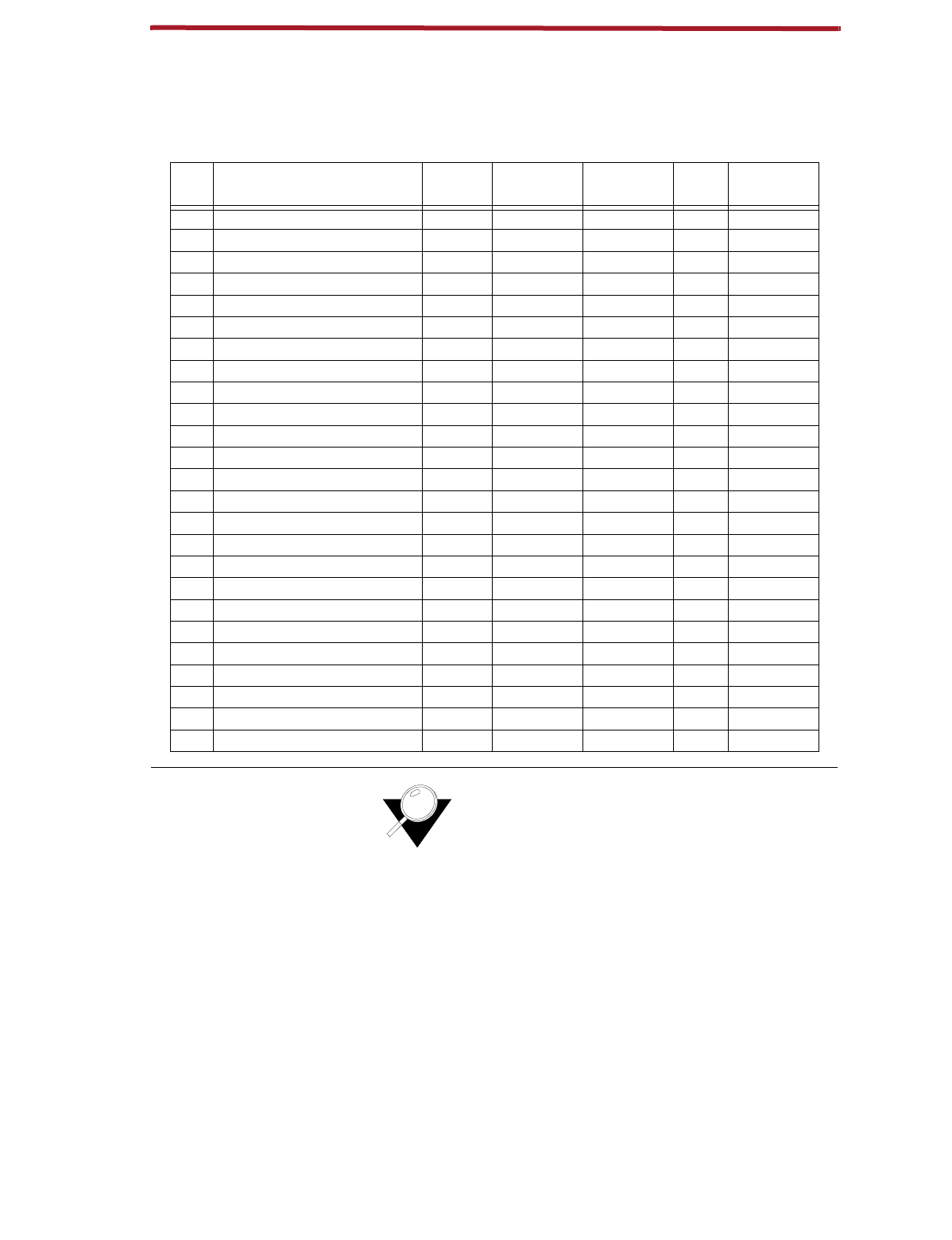
DCE DB25 Female Connector (Data Ports 1 and 2)
Note:
For purposes of connection and function,
the ICX-250 should be considered a DCE.
Pin Signal Name Mnemonic Source V.35 EIA-530A
1 Shield X
2 Transmit Data TXD+ BA (A) DTE X X
3 Receive Data RXD+ BB (A) DCE X X
4 Request to Send RTS+ CA (A) DTE X X
5 Clear to Send CTS+ CB (A) DCE X X
6 DCE Ready DSR+ CC DCE X X
7 Signal Common AB X X
8 Receive Line Signal Detector DCD+ CF (A) DCE X X
9 Receive Signal Element Timing RXCLK- DD (B) DCE X X
10 Receive Line Signal Detector DCD- CF (B) DCE X
11 Transmit Signal Element Timing (DTE) TXCLK DA (B) DTE X
12 Transmit Signal Element Timing (DCE) TXCLK- DB (B) DCE X X
13 Clear to Send CTS- CB (B) DCE X
14 Transmit Data TXD- BA (B) DTE X X
15 Transmit Signal Element Timing (DCE) TXCLK+ DB (A) DCE X X
16 Receive Data RXD- BB (B) DCE X X
17 Receive Signal Element Timing (DCE) RXCLK+ DD (A) DCE X X
18 Local Loopback LL LL DTE X
19 Request to Send RTS- CA (B) DTE X
20 DTE Ready DTR+ CD DTE X
21 Remote Loopback RL RL DTE X
22 Ring Indicator CE DCE X
23 Signal Common AC X
24 Transmit Signal Element Timing (DTE) TXCLK DA (A) DCE
25 Test Mode TM TM X