


48 Electrical Installation Power Requirements
ADCP-62-023 Issue 1, September 1998
© 1998, ADC Telecommunications, Inc.
Alarm
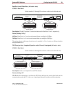
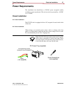
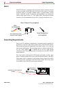
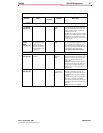
The ICX-250 unit is equipped with an external alarm connector (located
on the rear panel of the unit) that will close in the event of an alarm
condition such as: T1 failure, internal failure, or power failure. A Red
alarm is detected by the T1 interface and responded to by issuing the
yellow alarm signal on the T1. The figure below illustrates the alarm
connector. It is recommended you use 26 to 24 gauge twisted-pair wire.
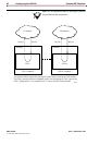
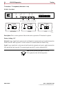
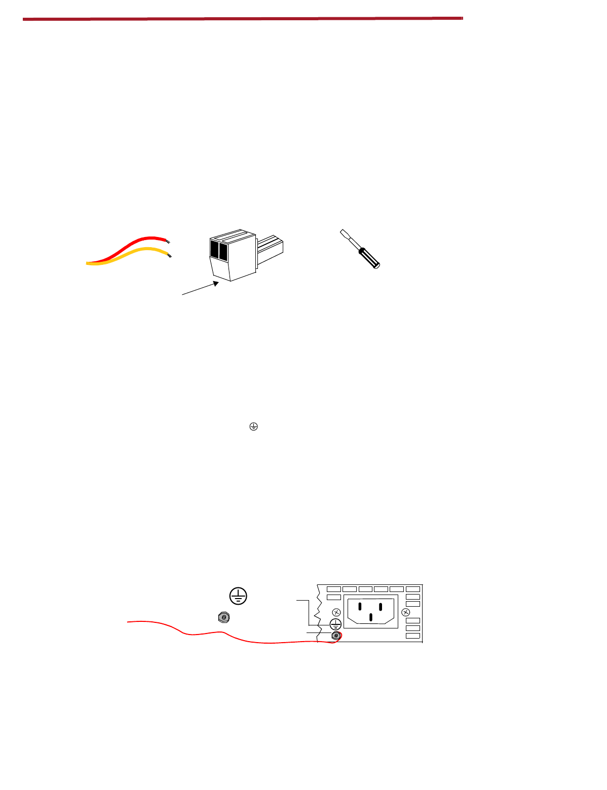
Grounding Requirements
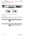
Due to the UL regulatory requirements, a mounting stud is required for
connection of the AC input earth ground lead to the ICX-250 chassis.
The ground lead must be connected to the chassis using a No. 6 nut and
lock washer combination. The mounting location is labeled with the IEC
417 No. 5019 symbol ( ) to identify this as the AC earth ground
connection point. This mounting stud is located next to the IEC 320 AC
input connector.
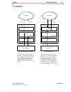
The loop battery return and the FXS digital and analog circuitry must
share a common ground. The access point on the back panel of the ICX-
250 product allows connection to an external battery return lead which
will be physically connected to the FXS circuit ground. This access point
is provided as part of the DC power input connector.
Small Screwdriver
Alarm Closure Plug (supplied)
Wire
wire ti
g
htenin
g
screws
(located under adapter)
(not supplied)
(not supplied)
120 VAC - .6A 60Hz
Groundin
g
Symbol
No. 6 nut
and lock washer
attached to external
g
round
location