


Switches Configuring the ICX-250 21
Issue 1, September 1998 ADCP-62-023
© 1998, ADC Telecommunications, Inc.
FXS Ports
Transmit
for 12 port model
(see page 26)
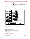
S14, S15, S16
positions 2, 4, 6
and 8
Internal 3 dB
9 dB
3 dB: Transmit path attenuated by
3 dB (+/– .5).
9 dB: Transmit path attenuated by
9 dB (+/– .5).
FXS Ports
Receive
for 12 port model
(see page 26)
S14, S15, S16
positions 1, 3, 5
and 7
Internal 3 dB
9 dB
3 dB: Receive path attenuated by
3 dB (+/– .5).
9 dB: Receive path attenuated by
9 dB (+/– .5).
FXS Ports
Transmit
for 24 port model
(see page 26)
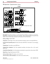
S17, S18, S19
positions 2, 4, 6
and 8
Internal 3 dB
9 dB
3 dB: Transmit path attenuated by
3 dB (+/– .5).
9 dB: Transmit path attenuated by
9 dB (+/–.5).
FXS Ports Receive
for 24 port model
(see page 26)
S17, S18, S19
positions 1, 3, 5
and 7
Internal 3 dB
9 dB
3 dB: Receive path attenuated by
3 dB (+/– .5).
9 dB: Receive path attenuated by
9 dB (+/– .5).
Trunk Conditioning
(per group of 12
lines)
(see page 28)
S6, S7
position 6
Internal Idle
Idle Imm./Busy
Idle: In the event of an alarm condi-
tion in the T1 connection to the net-
work, the FXS Ports will be put into
the idle state immediately and
remain in this condition until the T1
has been restored.
Idle Immediate/Busy: In the event
of an alarm condition in the T1 con-
nection between the ICX-250 and
the network, the FXS Ports will be
put into the Idle state immediately
for 3 seconds and then put in the
Busy state and remain in this condi-
tion until the T1 has been restored.
FXS Ringback Tone
(see page 29)
S6-S7
position 7
Internal On
Off
On: Ringback tones will be sent
on the corresponding DS0’s for the
duration of ringing on the line.
Off: Ringback provided by PBX
or Switch.
FXS Timeslot
Assignment
(see page 30)
S7 Only
position 8
Internal Off
Swap
Off: FXS Ports 1-12 are mapped
onto T1 timeslots 1-12 and FXS
Ports 13-24 are mapped onto T1
timeslots 13-24.
Swap: FXS Ports 1-12 are mapped
onto T1 timeslots 13-24 and FXS
Ports 13-24 are mapped onto T1
timeslots 1-12.
Depending on the services pro-
vided by your carrier for voice
and data, you may need to reas-
sign the FXS timeslots of the 12
FXS port model. Timeslots 13 to
24 will be assigned in order to
allocate data to the lower
timeslots.
FXS Ports
Loopback Operation
and/or Channel
Unassigned
(per line)
(see page 39)
S4-S5
S5 1-12 = 1-12
S4 1-12 = 13-24
Back On
Off
On: Breaks the connections to
and from the FXS and loops the
receive data back onto the transmit
path towards the T1. In the case
of unassigned channels, provides
an idle termination.
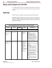
The bold highlighted selection under “Options” is the Factory Setting.
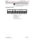
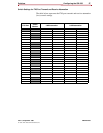
Function Switch
Switch
Location
Option Description