


External DIP Switches Configuring the ICX-250 31
Issue 1, September 1998 ADCP-62-023
© 1998, ADC Telecommunications, Inc.
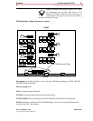
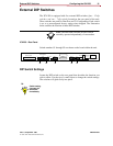
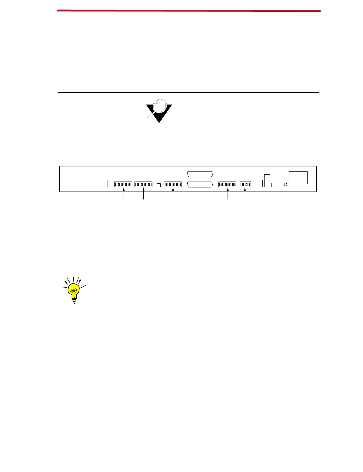
External DIP Switches
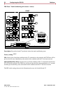
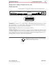
The ICX-250 is equipped with five external DIP switches
(four - 12 dip
switches, and one - 7 dip switch)
located on the rear panel of the unit.
These switches are used for Data Port and T1 Configuration. Each switch
is set to a preconfigured factory setting when shipped. The illustration
below outlines the location of these DIP switches.
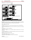
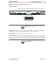
Note:
The individual switches on each switch
assembly operate independently of one another.
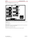
ICX-250 - Rear Panel
Switch numbers S1 through S5 are shown on the board within the unit.
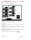
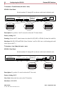
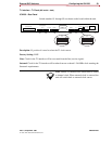
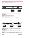
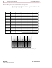
DIP Switch Settings
Locate the DIP switch on the rear panel that describes the function you
wish to effect. Use the tip of a small object to change the switch settings.
The switches will glide easily into place.
120 VAC–.6A 60Hz
24/48 VDC
+ – G
T1
Rx
Tx
T1 Line
T1Data 2Data 2Data 11121324
Alm.
Data 1
FXS Loopback
FXS Loop Pairs
11265-A
S5 S4 S3 S2 S1
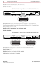
TIP
Switch setting
changes will
take effect
immediately.