


26 Configuring the ICX-250 Switches
ADCP-62-023 Issue 1, September 1998
© 1998, ADC Telecommunications, Inc.
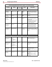
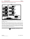
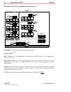
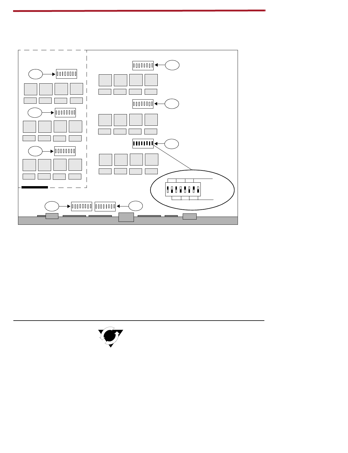
FXS Ports (per line) - Transmit / Receive
(
DIP switch - internal
)
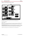
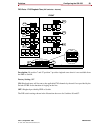
Description:
These are eight position DIP switches used to set Transmit and Receive FXS
attenuation (TLP Setting).
Factory Setting:
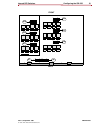
3 dB (OFF) The DIP switch layout shown above is an example using 3 dB of
attenuation on the Transmit side (positions 2,4,6,8 off) and 9 dB on the Receive side (positions
1,3,5,7 on). If it is necessary to change the Transmit setting to attenuate the line by 9 dB, the related
switch position(s) would be set to the “On” setting. Receive side settings would be changed from
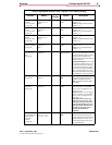
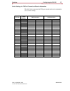
9 dB to 3 dB by moving the related switch position to “Off.” See the chart on page 27 for more detail
on the switch settings.
3dB:
Transmit / Receive path will be attenuated by 3 dB (+/
–
0.5).
9dB:
Transmit / Receive path will be attenuated by 9 dB (+/
–
0.5).
!!ATTENTION!!
The above FXS Port settings are
repeated for each of the 12 or 24 lines.
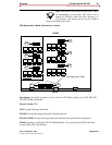
1 2 3 4 5 6 7 8
ON DIP
S7
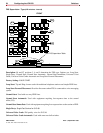
1 2 3 4 5 6 7 8
ON DIP
S6
1 2 3 4 5 6 7 8
ON DIP
S17
1 2 3 4 5 6 7 8
ON DIP
S18
1 2 3 4 5 6 7 8
ON DIP
S19
1 2 3 4 5 6 7 8
ON DIP
S14
1 2 3 4 5 6 7 8
ON DIP
S16
1 2 3 4 5 6 7 8
ON DIP
S15
S1
S2
S3
S4 S5
BACK
FRONT
S16
S15
S19
S18
S17
S14
S7
S6
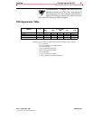
1 2 3 4 5 6 7 8
ON DIP
9 dB
3 dB
FXS Ports
Receive
4 3 2 1
Transmit
FXS Ports
4 3 2 1
Attenuation
Loss
(or Loss)