


36 Configuring the ICX-250 External DIP Switches
ADCP-62-023 Issue 1, September 1998
© 1998, ADC Telecommunications, Inc.
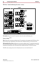
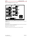
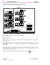
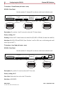
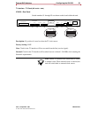
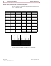
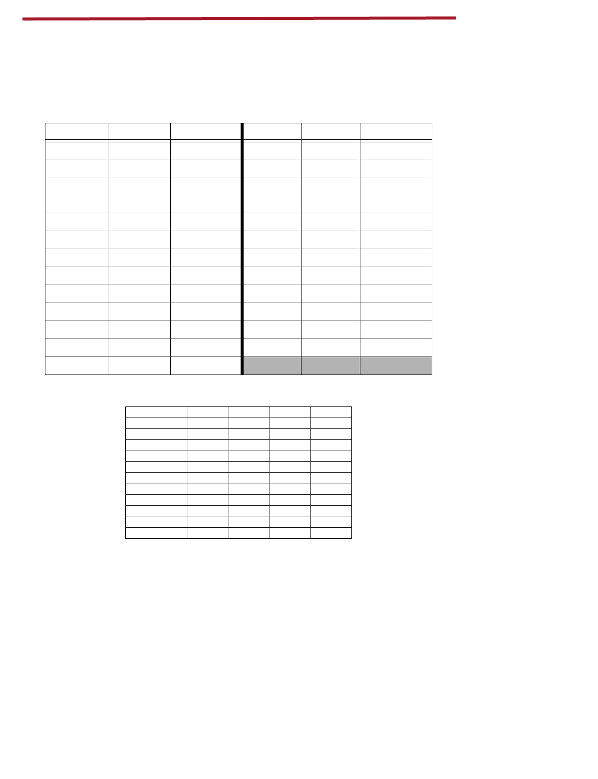
Decimal / Binary Conversion Table for Data Port Configuration
The table shown below illustrates the binary equivalent of Timeslots 1-24.
Note: 1 = ON and 0 = OFF.
This
table is used for selecting the starting timeslots for each data port.
Bandwidth Timeslot Switch Setting Bandwidth Timeslot Switch Setting
-- 0 00000 832K 13 01101
64K 1 00001 896K 14 01110
128K 2 00010 960K 15 01111
192K 3 00011 1024K 16 10000
256K 4 00100 1088K 17 10001
320K 5 00101 1152K 18 10010
384K 6 00110 1216K 19 10011
448K 7 00111 1280K 20 10100
512K 8 01000 1344K 21 10101
576K 9 01001 1408K 22 10110
640K 10 01010 1472K 23 10111
704K 11 01011 1536K 24 11000
768K 12 01100
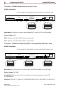
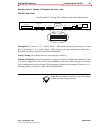
Starting T/S6789
1 off off off off
3 off off off on
5 off off on off
7offoffonon
9 off on off off
11 off on off on
13 off on on off
15 offononon
19 on off off on
21 on off on off
23 on off on on