


Appendix B: Specifications April 14, 2006
B-6 MM70xG2-UM-03
CONNECTOR PINOUTS
The following sections provide the pinout information for the various modem connectors.
•DSL Port (RJ-11)
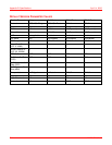
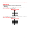
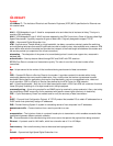
Table B-1 shows the signal on each pin of the DSL port for a 2-wire G.shdsl application. The connector for this
interface is an RJ-11. The modem accommodates Tip and Ring reversal on this one loop.
See Connect Cables on page 1-3 for the location of this port.
Table B-1. DSL Port (RJ-11) (2-Wire)
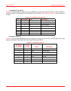
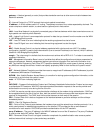
Table B-2 shows the signal on each pin of the DSL port for a 4-wire G.shdsl application. The connector for this
interface is an RJ-11. The modem accommodates Tip and Ring reversal on each separate Loop A and Loop B.
SeeConnect Cables on page 1-3 for the location of this port.
Table B-2. DSL Port (RJ-11) (4-Wire)
Pin Signal
1 Not used
2 No connection
3 Tip (Loop A)
4 Ring (Loop A)
5 No connection
6 Not used
Pin Signal
1 Not used
2 Tip (Loop B)
3 Tip (Loop A)
4 Ring (Loop A)
5 Ring (Loop B)
6 Not used