


April 14, 2006 Appendix B: Specifications
MM70xG2-UM-03 B-7
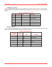
• 10/100Base-T Port (RJ-45)
Table B-3 shows the signal on each pin of the 10/100Base-T port connector when the switch is in either the MDI or
the MDI-X position. The connector for this interface is an RJ-45. See Connect Cables on page 1-3 for the location of
this port.
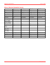
Table B-3. 10/100Base-T Port (RJ-45)
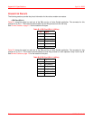
• Console Port (RJ-45)
Table B-4 gives the signal designations and pin numbers for each end of the RJ-45 to RS-232 cable that is used
between the modem Console port (RJ-45) and the PC Serial port (DB-9).
Table B-4. Console Port (RJ-45)
MDI MDI-X Signal Signal Description
1 3 TX+ Transmit Data (+)
2 6 TX- Transmit Data (-)
3 1 RD+ Receive Data (+)
4 4 Not used Not used
5 5 Not used Not used
6 2 RD- Receive Data (-)
7 7 Not used Not used
8 8 Not used Not used
PC RS-232
Serial (DB-9)
Modem
Console
(RJ-45) Signal Description
1
2 2 RXD Receive Data
3 3 TXD Transmit Data
4
5 5 GND Ground
6
7
8