


Chapter 1: Installation April 14, 2006
1-4 MM70xG2-UM-03
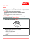
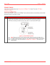
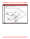
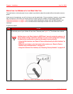
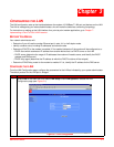
2 Connect the cables to the modem rear panel as shown below in Figure 1-3:
• Silver cable to the DSL line port and wall jack
• Black Ethernet cable to the 10/100Base-T port and to another Ethernet device such as a PC, hub,
or router
• Power cable to the modem power connector and to facility power
Figure 1-3. Rear Panel Connections
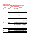
3 Refer to “LED Status Indications” on page 1-5 to verify modem status via LEDs.
Step Action