


108 IQ Probe User Manual 61200214L1-1
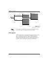
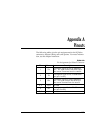
Appendix A. Pinouts
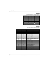
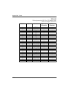
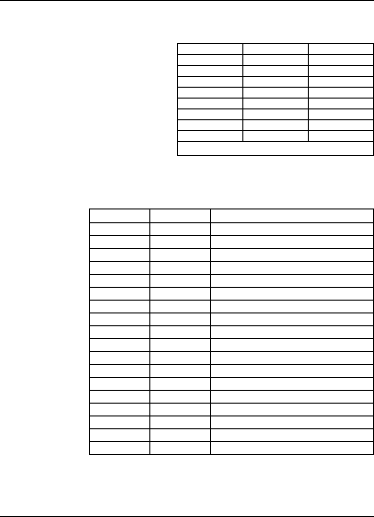
Table A-B
Pin Assignments for Control Connector
RJ Pin# Function Direction
1 GND
2 RTS I
3TD I
4 DSR O
5RDO
6 CTS* O
7 DTR I
8 DCD O
*Used for hardware flow control.
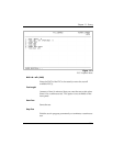
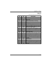
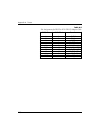
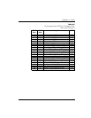
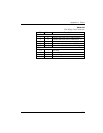
Table A-C
EIA -232 Connector Pin Assignments
Pin EIA Description
1 AA Protective Ground (PG)
2 BA Transmit Data (SD)
3 BB Receive Data (RD)
4 CA Request to Send (RS)
5 CB Clear to Send (CS)
6 CC Data Set Ready (SR)
7 AB Signal Ground (SG)
8 CF Received Line Signal Detector (CD)
9 - +12 Test Point
10 - -12 Test Point
15 DB Transmit Clock (TC)
17 DD Receive Clock (RC)
18 - Local Loopback (LL)
20 CD Data Terminal Ready (TR)
21 - Remote Loopback (RL)
22 CE Ring Indicator (RI)
24 DA External Tx Clock (ETC)
25 - Test Indicator (TI)