


34 IQ Probe User Manual 61200214L1-1
Chapter 4. Applications
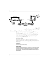
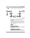
During dial backup, the IQ device receiving the call continues to
use the frame relay circuit for PVCs that are not affected by the
outage, while using the DBU interface for PVCs that are inactive
due to the outage. This is done (without the attached DTE
device's intervention) by modifying the status of PVCs that are
in DBU state to active when the PVC status is given to the DTE.
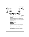
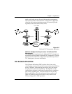
An IQ Probe with multiple PVCs to multiple sites can also
originate a call to one site during an outage and restore connec-
tion for PVCs to that destination. Since the IQ Probe can only
make one call at a time, the other PVCs to other sites in this
scenario will be inactive.
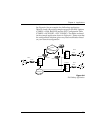
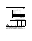
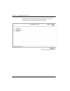
Information entered into the PVC Configuration Table (see Table
4-B) marks PVCs for DBU operation. The key element in each
entry of the table is the DBU DLCI. For each PVC connecting
two sites for DBU operation, the DLCI field represents the PVC
DLCI at the local UNI and the DBU DLCI represents the PVC
DLCI at the remote site UNI. The IQ Probe uses this information
in the outbound side to change the PVC DLCI so the far end
DTE device receives frames on the DBU PVC addressed in the
same manner as when the frame relay circuit is operational. For
PVCs not used for DBU operation, leave the DBU DLCI field set
to zero.
The DBU DLCI information is only required for the IQ Probe
originating the call. In cases such as remote sites establishing
calls to host sites, the remote site should have only non-zero
values for the DBU DLCI fields in the PVC Configuration Table.
Only PVCs that are used in DBU should have the DBU DLCI set to a
non-zero value.
The range for the DBU DLCI field is from 16-1007. Therefore,
you cannot manually enter 0 for the PVCs not used in DBU.
When an entry is first created with the ADD selection, it is set to
0 by default. To reset a previously configured DBU DLCI to 0,
delete the entry and then add it back in (using the DELETE and
ADD selections).