


61200214L1-1 IQ Probe User Manual 11
Chapter 2. Installation
DBU Interface Card Slot
The IQ Probe rear panel has one card slot (labeled DBU INTER-
FACE) for the installation of dial backup and DCE cards. To
insert cards, perform the following procedure:
1. Remove power from the IQ Probe.
2. Slide the card into the DBU Interface rear slot until the card
panel is flush with the IQ Probe chassis.
3. Push card locks in (until they click) to secure the card and
ensure proper installation.
Remove power from the unit prior to installing or removing option
cards.
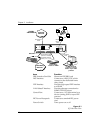
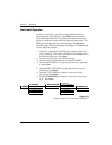
DCE Interface
Connect the IQ Probe to the dedicated frame relay circuit
through a DSU/CSU connected to the IQ Probe DCE port. The
port provides an EIA-232 or EIA-530 interface (using a standard
DB-25 cable) or it can be cabled to an X.21 or V.35 interface
(using optional ADTRAN adapter cables). Part numbers for the
adapter cables are listed earlier in this section. The pinouts for
this connector and for the adapter cables are listed in the
appendix Pinouts.
DTE Interface
Connect a FRAD/router to the DTE port using a standard DB-25
cable (for EIA-232 or EIA-530) or an ADTRAN adapter cable (for
X.21 or V.35). Part numbers for the adapter cables are listed
earlier in this section.
The maximum cable lengths recommended are 15 meters for
EIA-232, 60 meters for EIA-530, 60 meters for X.21, and 30 meters
for V.35. The pin assignments for this connector and for the
adapter cables are listed in the appendix Pinouts.