27
G
E
F
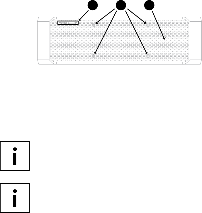
Fig. 7: Front view of the external optional battery unit
EXPLANATIONS:
A UPS model series plate with power rating in VA
B Status display (different colored LEDs)
C Graphical LCD display for alphanumeric display
D Operating keys for menu navigation
A detailed explanation of the operating panel can be found in chapter 7.2
on page 43.
E Locking screws to fasten the front panel
Behind the front panel (with the exception of the battery unit D. 10000 BP),
you will find the terminals for the integrated batteries.
F Air vent (do not cover)
G Name of the external battery extension


