


29
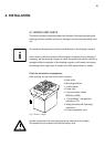
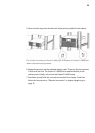
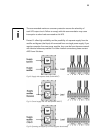
EXPLANATIONS:
1 Locking screws for the removable connection unit
2 Power input – separate connection of bypass (2.1) and rectifier unit (2.2)
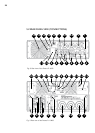
is possible (dual input)
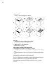
The feed can be run either from the rear-side or from the top of the cable glands
(illustration shows rear-side). If only one cable is to be laid, the portable bypass
feed (1.2) remains unused.
3 UPS output (load) over fixed connection
4 Locking screws for securing the bracket built into the manual bypass switch
connection unit
5 Manual bypass switch
6 Consumer connection via IEC60320 C19 sockets, automatic arrestor fitted
with an upstream fuse
7 Consumer connection via IEC60320 C13 sockets, automatic arrestor fitted
with an upstream fuse
Taken from the consumer line by pressing the respective push button output of
each IEC socket.
8 RS232 communication interface (sub-D9 jack)
9 USB communication interface
10 Communication slot for optional extension cards:
Relay card, card for remote on / off, SNMP, …
The USB and the RS232 communication interfaces cancel each other out, i.e.
either USB or RS232. The communication slot is dual-monitor enabled, i.e. can
be used parallel to the USB or RS232 interface.