


34
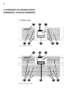
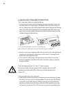
6.3 MAINS AND CONSUMER CONNECTION
The in- and output cables are installed as follows:
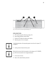
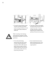
• Connect the unit directly from the packaging for easier assembly, unscrew the
rear strain relief screw. Depending on the desired cable entry (from the top or
rear, e.g. dependent on the cabinet depth) break open the appropriate blanking
plates. If the UPS will be operated with two separate power cords, then break
open all three blanking plates; otherwise leave them untouched apart from the
outside left (bypass) blanking plate.
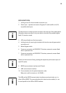
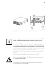
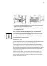
• Strip the incoming and outgoing cables (after the onset of the cable glands) and
feed them into the terminal compartment of the Protect D. ensuring that the
proper strain relief glands are used.
• The cores of the cables hang at the appropriate terminal block. Ensure that
ferrules are applied to the cables ends before connection. Begin by installing
the ground (earth).
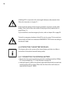
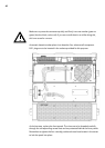
Check the bridges between “JP” and “L” (Feed-in bypass)
Remove the bridge unless you want to feed the bypass input of the UPS
separately or to operate the UPS in frequency converter operation (refer
chapter 6.2)
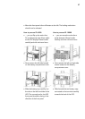
• Remove cable scrap, tools, screws etc.
• Install the previously removed strain relief gland back onto the Protect D. Make
sure that you do not crush the individual cables. Fix the rear right side (D.6000)
or rear left and right side (Protect D.10000) remaining mounting brackets for
later fixing of the terminal unit. Finally, with the aid of the guide pins, plug the
connector unit to the rear of the UPS and lock unit with the outer fixing screws.
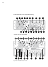
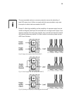
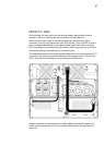
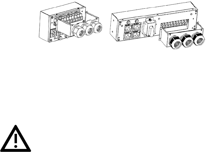
Fig. 13: Left, the detachable connection of the D. 6000 unit.
Right the Protect D. 10000, each shown with rear cable entry and dual-input.