39
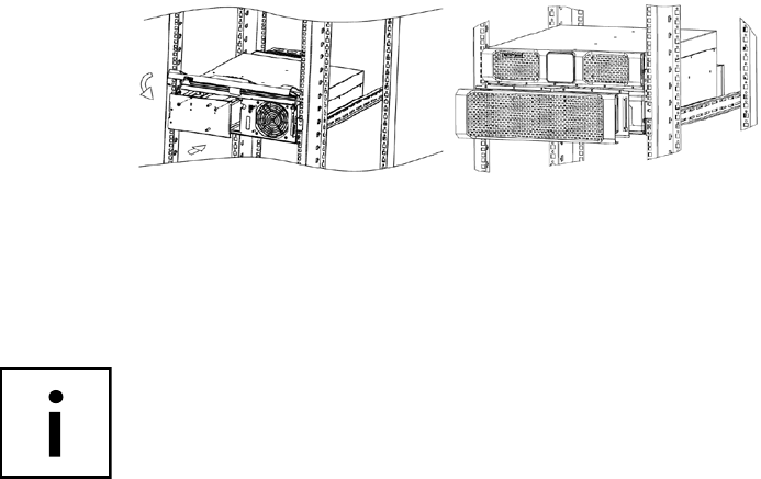
• As a final step, remember to tighten the four centrally positioned cross-head
screws in the center to lock the panel into place.
• Finally, slide the UPS completely into the rack and attach the UPS on the side
with the supplied screws.
6.4.2 CONNECTING EXTERNAL BATTERY EXTENSION(S)
The connection of the optional external battery unit(s) for the Protect D. 6000
takes place on the front, while on the D. 10000 it takes place at the rear. Due
to the different procedure for connecting the two variants, each is therefore
described separately in separate chapters.
PROTECT D. 6000
The front panel of the Protect D. 6000 should still be in the open folded up state.
Now remove the slot cover at the bottom of the UPS front cover.
Similarly to the UPS, also remove to the front panel(s) of the external battery
pack(s). Each front panel has a top and bottom slot cover. Now remove the top
slot cover on the front panel. If you are using more than one battery unit, remove
both slot covers in the remaining front panels so that you can wire the battery
units all the way through.
Now start to lay the battery wiring according to the following diagram. The
electrical connection takes place via the connection of the respective battery
connectors (each consisting of one green, one black and one red male): green
to green, black to black, red to red.


