


Names of Parts
2-3
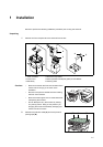
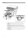
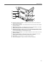
20 Document Processor Connector — Attach the connection cable here when installing the
optional document processor.
21 Parallel Interface Connector — Use a parallel cable to connect the connector with a parallel
port of your computer.
22 USB Interface Connector — This USB interface conforms to Hi-Speed USB2.0. Use a USB
cable to connect this connector with a USB port of your computer.
23 Right Cover Anchor Pin — This pin must be removed and the right cover opened in order to
access the slot for installing additional memory. If you need to add additional memory, contact
your service representative or an authorized service center.
24 Network Interface Connector — Use a 10Base-T/100Base-TX network cable to connect the
machine to a network.
25 Rear Cover (Face-up Tray) — When the rear cover is open, it is used as the face-up tray.
Finished copies or printouts can be ejected and stored face-up on this tray.
26 Power Switch — Turn this switch on ( | ) before using this machine.
27 Power Cord Receptacle — Plug the AC Power Cord into this respectable.
26
24
27
20
23
21
22
25