


C.2 Serial Interface Specifications
Table C–1 lists the pin signals for the RS232C serial interface connector.
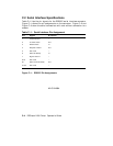
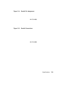
Figure C–1 shows the pin assignments on the connector. Figure C–2 and
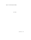
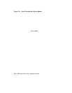
Figure C–3 show the serial connections with and without connection to a
modem.
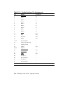
Table C–1: Serial Interface Pin Assignment
Pin Signal Direction
1 Frame Ground –
2 Transmit Data Out
3 Receive Data In
4 Request to Send Out
5 Not Used –
6 Data Set Ready In
7 Signal Ground –
8–19 Not Used –
20 Data Terminal Ready Out
21–25 Not Used –
Figure C–1: RS232C Pin Assignments
MLO-004884
C–4 DEClaser 2100 Printer Operator’s Guide