


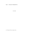


Table 1–2: Printer Components: Rear/Left-Side View
Component Function
1. Power Switch Powers the printer on or off. Pressing ‘‘|’’ turns
power on; pressing ‘‘O’’ turns power off. To ensure
that data is not lost, always be sure the display reads
00 READY and the Data indicator is off, before you
power off the printer. See Section 2.1 and Section 2.2
for additional information about powering the printer
on and off.
2. Rear Output Tray
(shown closed)
The rear output tray is selected when you are using
certain types of print media such as transparencies
and labels. It can also be used when you want printed
output to be stacked faceup. Refer to Section 2.5 for
information about choosing the different output trays.
See Section 2.5.2 for information about opening and
using the rear output tray.
3. Memory Board Access Cover Additional RAM (random-access memory) can be
added to the printer in 1, 2, or 3 MB capacities.
This access cover allows you to easily install the
extra memory board. Refer to the documentation that
comes with the optional memory board for installation
instructions.
4. Parallel (Centronics)
Interface Cable Connector
This connector is used when the interface cable from
the host computer is a parallel cable. Refer to the
DEClaser 2100 Printer Installation Guide for more
information about connecting your computer to the
printer.
5. Serial (RS232)
Interface Cable Connector
This connector is used when the interface cable from
the host computer is a serial cable. Refer to the
DEClaser 2100 Printer Installation Guide for more
information about connecting your computer to the
printer.
6. Power Cord Receptacle This is where the power cord is connected to the
printer.
Printer Components 1–5