


The values stored in the preamble represent the captured data currently
stored in this structure and not the current analyzer configuration. For
example, the mode of the data (bytes 33 and 103) may be STATE with
tagging, while the current setup of the analyzer is TIMING.
The next 70 bytes are for Analyzer 1 Data Information.
Byte Position
33 4 bytes - Machine data mode in one of the following decimal values:
−1 = off
0 = 100 MHz State data, no tags
1 = 100 MHz State data, tag data in
unassigned pod
2 = 100 MHz State data, tag data
interleaved with acquired data
10 = conventional timing data on all channels
13 = conventional timing data on half channels
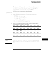
37 4 bytes - List of pods in this analyzer, where a binary 1 indicates that the
corresponding pod is assigned to this analyzer
bit 31 bit 30 bit 29 bit 28 bit 27 bit 26 bit 25 bit 24
unused unused unused unused unused unused unused unused
bit 23 bit 22 bit 21 bit 20 bit 19 bit 18 bit 17 bit 16
unused clock
pod 2
clock
pod 1
unused unused unused unused unused
bit 15 bit 14 bit 13 bit 12 bit 11 bit 10 bit 9 bit 8
unused unused unused unused unused unused unused Pod 8
bit 7 bit 6 bit 5 bit 4 bit 3 bit 2 bit 1 bit 0
Pod 7 Pod 6 Pod 5 Pod 4 Pod 3 Pod 2 Pod 1 unused
Example xxxx xxxx x01x xxxx xxxx xxx0 0001 111x indicates that data
pods 1 through 4 and clock pod 1 are assigned to this analyzer (x = unused
bit).
DATA and SETup Commands
Data Preamble Description
27–7