


12 AT-IFS802SP/POE(W)-80 User Manual
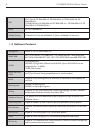
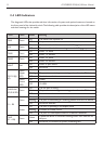
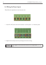
2.4 LED Indicators
The diagnostic LEDs that provide real-time information of system and optional status are located on
the front panel of the industrial switch. The following table provides the description of the LED status
and their meanings for the switch.
LED Color Status Meaning
PWR Green
On The switch unit is power on
Off No power
R.M. Green
On The industrial switch is the master of X-Ring group
Off The industrial switch is not a ring master in X-Ring group
PWR1 Green
On Power 1 is active
Off Power 1 is inactive
PWR2 Green
On Power 2 is active
Off Power 2 is inactive
FAULT Red
On Power or port failure
Off No failure
P9, P10 (RJ-
45)
Green
(Upper
LED)
On A network device is detected.
Blinking The port is transmitting or receiving packets from the TX device.
Off No device attached
Green
(Lower
LED)
On 1000M
Off 10/100M
Link/Active
(P9, P10 SFP)
Green
On The SFP port is linking
Blinks The port is transmitting or receiving packets from the TX device.
Off No device attached
P1 ~ P8
Green
On A network device is detected.
Blinking The port is transmitting or receiving packets from the TX device.
Off No device attached
Amber
On The port is operating in full-duplex mode.
Blinking Collision of Packets occurs.
Off The port is in half-duplex mode or no device is attached.
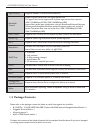
FWD
(P1 ~ P8)
Green
Green
A powered device is connected utilizing Power over Ethernet on
the port
Off No device is connected or power forwarding fails