


13AT-IFS802SP/POE(W)-80 User Manual
Chapter 3 Hardware Installation
In this paragraph, we will describe how to install the 8 10/100TX w/ X-Ring Managed Industrial Switch and
the installation points attended to it.
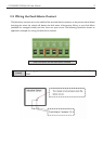
3.1 Installation Steps
Unpack the Industrial switch1.
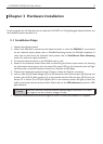
Check if the DIN-Rail is screwed on the Industrial switch or not. If the2. DIN-Rail is not screwed
on the Industrial switch, please refer to DIN-Rail Mounting section for DIN-Rail installation. If
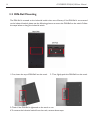
users want to wall mount the Industrial switch, please refer to Wall Mount Plate Mounting
section for wall mount plate installation.
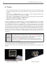
To hang the Industrial switch on the DIN-Rail track or wall.3.
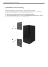
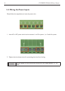
Power on the Industrial switch. Please refer to the Wiring the Power Inputs section for knowing 4.
the information about how to wire the power. The power LED on the Industrial switch will light
up. Please refer to the LED Indicators section for indication of LED lights.
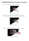
Prepare the twisted-pair, straight through Category 5 cable for Ethernet connection.5.
sert one side of RJ-45 cable (category 5) into the Industrial switch Ethernet port (RJ-45 port) and 6.
another side of RJ-45 cable (category 5) to the network device’s Ethernet port (RJ-45 port), ex:
Switch PC or Server. The UTP port (RJ-45) LED on the Industrial switch will light up when the
cable is connected with the network device. Please refer to the LED Indicators section for LED
light indication.
When all connections are set and LED lights all show in normal, the installation is complete.7.
[note]
Make sure that the connected network devices support MDI/MDI-X. If it does
not support, use the crossover category-5 cable.