


78 AT-IFS802SP/POE(W)-80 User Manual
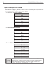
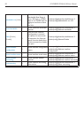
RJ-45 Pin Assignments of POE
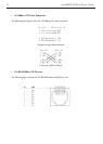
With 100BASE-TX/10BASE-T cable, pins 1 and 2 are used for transmitting data, and pins 3 and 6 for
receiving data; pins 4, 5, 7 and 8 are used for power supplying.
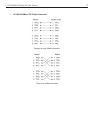
Pin Signal
1 RX+
2 RX-
3 TX+
4 VCC -
5 VCC -
6 TX-
7 VCC +
8 VCC +
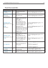
Pin out of Cisco non-802.3af standard PD•
Pin Signal / Name
1 RX+
2 RX-
3 TX+
4 VCC+
5 VCC+
6 TX-
7 VCC-
8 VCC-
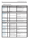
Pin out of PoE Midspan Hub/Switch•
Pin Signal / Name
1 TX+/VCC+
2 TX-/VCC+
3 TX+/VCC-
4
5
6 TX-/VCC-
7
8
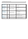
Pin out of PoE Endspan Hub/Switch•
[note]
‘+’and‘-‘signsrepresentthepolarityofthewiresthatmakeupeachwirepair.
Before you power PD, please check the RJ-45 connector pin assignment follow
IEEE802.3af standard; otherwise you may need to change one of the RJ-45
connector pin assignment attached with the UTP cable.