


1-2
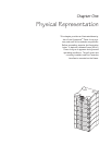
Chapter 1 - Physical Representation
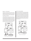
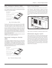
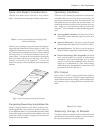
Powerview User Interface
The Powerview incorporates a 4 x 20 alphanumeric LCD screen
with four navigation keys, four LED status indicators, and an
audible alarm beeper. The display communicates with the
Power Array via a local RJ45 connector cable that is hardwired
into the top power module bay. It can be mounted on the
front of the frame, stand on top of the frame, or it can be
installed at a remote location. (A 20’ RJ45 cable is provided,
and plugs into a communication port at the rear of the frame.)
The alphanumeric LCD screen displays system status, fault
reporting and module diagnostics information. The naviga-
tion keys are used to scroll through an elaborate menu. Chap-
ter 6 provides detailed information about the Powerview.
Fig 1-3 Powerview User Interface
Alarm thresholds and parameters are set with the Powerview.
In the event of an alarm condition, the Powerview emits both
audible and visual alarm indicators.
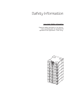
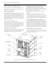
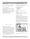
Louvered Grill Covers
Each level of the frame is equipped with a louvered grill cover.
These covers are interchangable, and snap securely onto the
frame. When removing, temporarily storing, and replacing
grill covers, use care to prevent them from being marred or
scratched.
Fig 1-3 Front Grill Cover Removal and Replacement
LED Status Indicators
LCD Screen
Navigation Keys
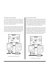
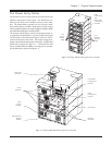
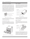
Power Module
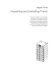
The power module is a self-contained, 4kVA UPS (without
batteries) housed inside a metal enclosure. A blind mating
connector at the rear of the module engages with a connector
inside the frame, and powers the unit. Power modules are
installed in the vertical column of bays at the left of the frame.
These bays are labelled L1, L2, L3, etc.
Fig 1-4 Power Module
In the event of a power module failure, the Powerview initiates
an audible alarm, and displays an error message. The power
module is hot-swappable. Instructions for module replace-
ment are provided in chapter 8.
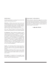
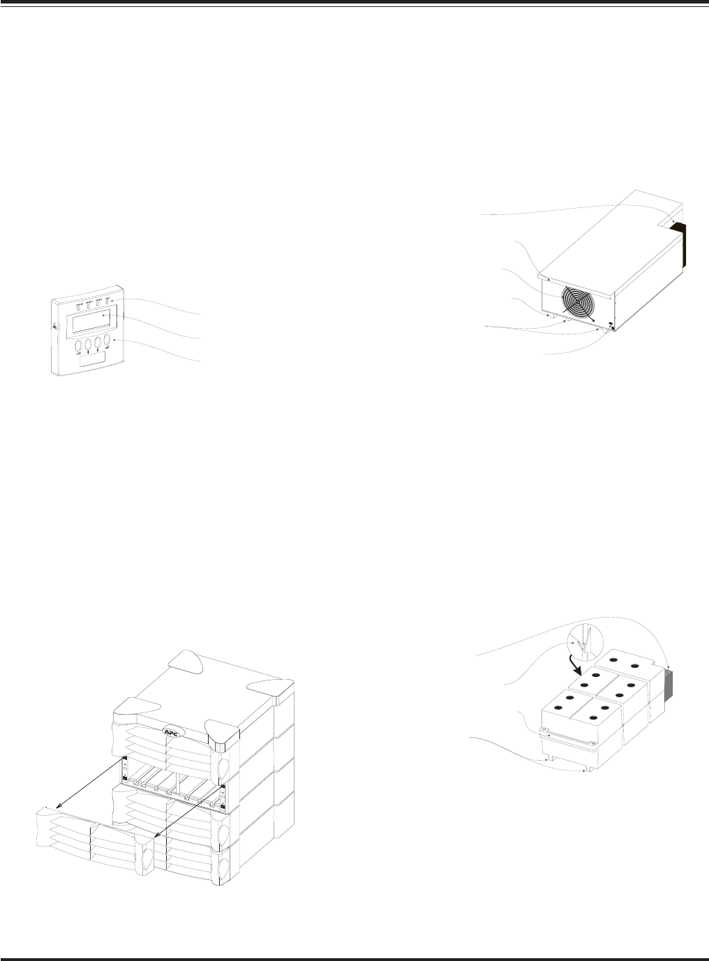
Battery Module
The battery module is comprised of a series of ten 12V batter-
ies housed inside a plastic enclosure. A blind mating connec-
tor at the rear of the module engages with a connector inside
the frame.
Fig 1-5 Battery Module
Battery modules are installed in the vertical column of bays at
the right of the frame. These are labelled R2, R3, R4, etc. (The
top right bay houses the intelligence modules.) The condition
and charge of each battery module is reported on the
PowerView. If a battery module fails, an alarm is initiated.
Battery modules are hot-swappable, and user replaceable.
Blind Mating
Connector
Positioning Handle
Cooling Fan Grill
Alignment Runner
Seating Tabs
Flip Latch Micro Switch
Blind Mating
Connector
Retaining Flange
Positioning Handle
Runners