


ii
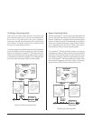
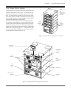
Power Processing System
The power processing system delivers conditioned AC output
power with a low distortion sinewave. Under normal operat-
ing conditions, power is received from the AC utility power
source, conditioned by the power processing system, and de-
livered to the load equipment. In the event of an AC utility
source failure, the power processing system receives power
from the battery source (battery modules), converts it to con-
ditioned AC, and delivers it to the load equipment. When AC
utility power is present, the power processing system also
maintains the battery source at full charge.
The power processing system in Symmetra
TM
is comprised of
individual power module(s). Each power module contains
the electronics for a complete 4kVA UPS, including the rectifier,
charger and inverter. When two or more power modules are
present, they operate in parallel, sharing the load equally.
By configuring the system with at least one more power mod-
ule than is required to power the load (a redundant power
module), Symmetra
TM
can sustain a power module failure,
and still deliver full power to the load equipment. The failed
module is identified by the control/user interface system, an
alarm is initiated to notify the user of the module failure, and
the hot-swappable module can be replaced by the user, with-
out the need to power down the load equipment.
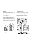
A Symmetra
TM
MiniFrame provides bays for up to three power
modules, and a MasterFrame provides bays for up to five.
This provides the full system capacity (8kVA and 16kVA re-
spectively), plus one redundant power module.
Battery Source
The battery source is comprised of parallel, hot-swappable,
120V battery modules. These are housed in the Symmetra
TM
frame, and in an optional extension battery frame.
A Symmetra
TM
MiniFrame provides bays for up to two bat-
tery modules, and a MasterFrame provides bays for up to
four. Both of these frames can be connected to an extension
battery frame. Additional battery modules increase on-bat-
tery run time.
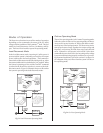
Control/User Interface
The control/user interface system coordinates the operation
of the Symmetra
TM
and reports status conditions via several
user interface options. Functions performed by the control/
user interface component include module coordination and
state control, analysis and reporting of system status, and
reporting of alarm conditions.
Module Coordination & State Control - The Symmetra
TM
incorporates a main intelligence module (MIM) that continu-
ously monitors the system, and delivers data to both the
PowerView user interface, and to the communication ports.
The MIM coordinates the initial power up of the system, trans-
fers it into and out of bypass mode, transfers the power source
between the utility AC power, and the battery source, and co-
ordinates shutdown operations.
System Status Monitoring - The MIM gathers data about the
system components, and delivers it to both the PowerView
interface, and to the computer interface ports. System status
monitoring and reporting data include the current predicted
run time, the status of individual battery modules and power
modules, input & output voltage, input & output voltage fre-
quency, and the size and status of the current output load.
Alarm Condition Detection - The control/user interface sys-
tem monitors the Symmetra
TM
for alarm conditions. If an
alarm condition is detected, the PowerView user interface ini-
tiates an audible and visual alarm. Alarm conditions include
on-battery, low battery, module faults, overloads, loss of re-
dundancy and a variety of other default and user defined events.
All possible alarm messages and the appropriate user responses
are provided in chapter 10.
Transformer
The power processing system receives either 208V or 240V
input AC utility power, and delivers 240V power to an internal
transformer. The transformer delivers multiple output volt-
ages (120V/208V/240V) to an output wiring terminal block
inside the Symmetra
TM
frame. Output wiring procedures are
provided in chapter 4.