


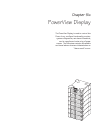

The PowerView Display
The PowerView Display is the primary user interface for the
Symmetra
TM
Power Array system. It is used to control the
Power Array, to configure the functionality, monitor the sys-
tem, set alarm thresholds, and it performs as the audible and
visual alarm.
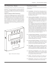
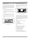
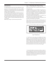
Physical Features of the Powerview
The PowerView Display incorporates a 4 x 20 LCD with four
navigation keys, four LED lights, and an audible alarm beeper.
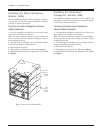
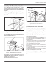
It is designed to either mount on the front of the frame, to
stand on top of the frame, or to be installed at a remote loca-
tion. A local RJ45 connector cable is hardwired to the top
power module bay (L1), and is used to connect the display
when it is mounted onto the frame. A 20’ RJ45 cable is pro-
vided with the system for positioning the PowerView at a re-
mote location.
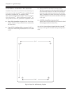
Fig 6-1 The PowerView Interface
PowerView Functions
An overview of each of the PowerView interface functions is
provided below:
n User Interface - The PowerView is the primary user in-
terface for the system. It is used to command the system
to power up, and power down the load, as well as to check
the status of system components, and to configure the
functionality of the system.
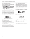
n Alarms and Alarm Thresholds - The PowerView con-
tains an audible and visual alarm system. In the event of
a power disturbance, or loss of a system component, (and
other user-configured alarm conditions), the PowerView
interface emits both an audible alarm and displays a vi-
sual message.
As an example, if a Power Array has been configured with
an N+1 redundancy, the PowerView can be configured so
that an audible alarm will sound if the system looses the
redundant power module. (Typically, this would be the
result of an additional load being added, or a power mod-
ule failure.) Other user configurable alarms include load
size threshold and minimum runtime threshold. Proce-
dures for setting user configurable parameters are pro-
vided in Chapter 7. All PowerView display messages, and
the corrective actions are listed in Chapter 9.
n Set System Function Parameters - The PowerView can
be used to set parameters for the functioning of the Power
Array. These include acceptable input and output fre-
quency ranges, frequency of self tests, and minimum/
maximum settings for power transfers.
n Powerview Interface Parameters - The PowerView can
be used to set the contrast of the LCD screen, select the
information that is displayed in the startup screen, set the
time, date, password and the audible alarm volume.
n Event Logging - The last 64 power and user events are
recorded and accessible via the PowerView interface. The
category of events that are logged is configurable. Statis-
tics are compiled and can be reviewed using the PowerView.
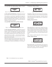
n Check Status and Diagnostics - Input voltage, output
voltage, available runtime, load size, current operating
mode and the status of each power and battery module
are reported by the PowerView interface.
n Testing - The PowerView interface can be used to per-
form a system self test and to simulate a power failure.
n Help Function - Pressing the up and down navigation
keys simultaneously launches context sensitive help.
Chapter 6 - The PowerView Display
6-1