Step 6: Configure Alarms
Specific alarm parameters can be configured into the
PowerView. Follow this procedure to set the alarm thresh-
olds that best fit the data center requirements.
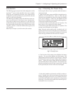
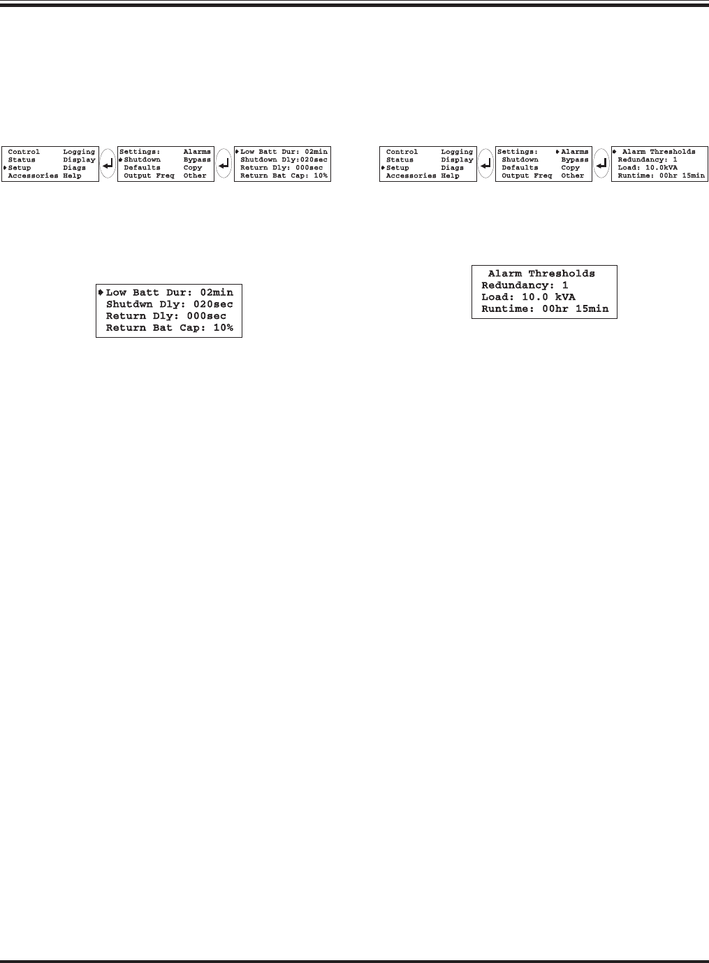
Use the following sequence on the PowerView to open the
alarm thresholds selection screen:
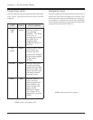
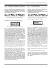
Fig 7-16 Opening the Alarm Thresholds Selection Screen
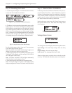
Alarm Thresholds Selection Screen
Fig 7-17 Alarm Threshold Selection Screen
Each line of the alarm threshold selection screen contains a
configuration parameter. To set a parameter, select a line
and press the enter key. Note the flashing up/down arrow
appears. Select a desired alarm parameter by scrolling up or
down through the choices using the arrow navigation keys.
When the desired parameter is displayed, press the enter key.
The parameter is then recorded into the PowerView memory.
Line #1: Redundancy Alarm Threshold - The Power Array
will signal an alarm if redundancy falls below this threshold.
Base this selection on the number of power modules present
(4kVA each), the size of the load, and the power module re-
dundancy requirements. If redundant power modules are
installed, it is highly recommended that this threshold be set
so that the alarm will be initiated if the redundancy is lost.
(Possibly as a result of an unauthorized increase of the load.)
Line #2: Maximum Load Threshold - The maximum load
threshold can be set, in increments of 2kVA. If the load ex-
ceeds this threshold, the alarm will sound.
Line #3: Minimum Run Time Threshold - The minimum
available run time threshold can be set. In the event that the
predicted run time falls below this threshold, the alarm will
sound.
Switching Audible Alarm Beeper Off
Use the following sequence to access the beeper alarm on/off
command: “Top level menu-Display-Beeper-Vol-select off.”
Note: This silences the audible alarm. It does not resolve the
alarm situation.
Step 5: Configure Shutdown Parameters
Specific shutdown parameters can be configured into the
PowerView. Follow this procedure to configure the shutdown
parameters that best fit best fit the data center requirements.
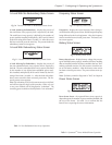
The following sequence on the PowerView opens the shut-
down parameter selection screen:
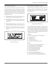
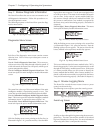
Fig 7-14 Shutdown Parameter Selection Sequence
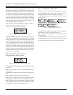
Shutdown Parameter Selection Screen
Fig 7-15 Shutdown Parameter Selection Screen
Each line of the shutdown parameter selection screen con-
tains a configuration parameter. To set a parameter, select a
line and press the enter key. Note the flashing up/down arrow
appears. Select the desired parameter by scrolling up or down
through the choices using the arrow navigation keys. When
the desired parameter is displayed, press the enter key. The
parameter is then recorded into the PowerView memory.
Line #1: Low Battery Duration - When in the on battery mode,
the Power Array will signal an alarm 2, 5, 7 or 10 minutes
before system shutdown occurs due to battery exhaustion.
Make selection based on the time required to gracefully shut-
down the load equipment in the data center.
Line #2: Shutdown Delay - many computer networks that
issue shutdown commands will require some additional run
time after that command is issued to gracefully shut them-
selves down. If your computer network is one of these, the
Power Array provides a choice of a 20, 180, 300 or 600 second
delay from the receipt of the shutdown command, to when
the Power Array stops powering the load equipment.
Line #3: Return Delay - when utility power is restored after a
failure, a delay interval may be desirable, to allow utility power
to stabilize before the system goes back on line. The return
delay interval can be set to 0, 60, 180 or 300 seconds.
Line #4: Return Battery Capacity - When returning from an
extended power failure, a minimum battery capacity is often
desired before repowering the load. The settable values for
this paramer are 0, 10, 25 and 90%. This minimal require-
ment insures there will be sufficient battery run time to safely
shutdown the load in the event of a subsequent power failure.
Press the enter key to record your selection, and then press
escape to return to the startup screen.
Chapter 7 - Configuring & Operating the Symmetra
TM
7-5


